ATX Power Supply Conversion
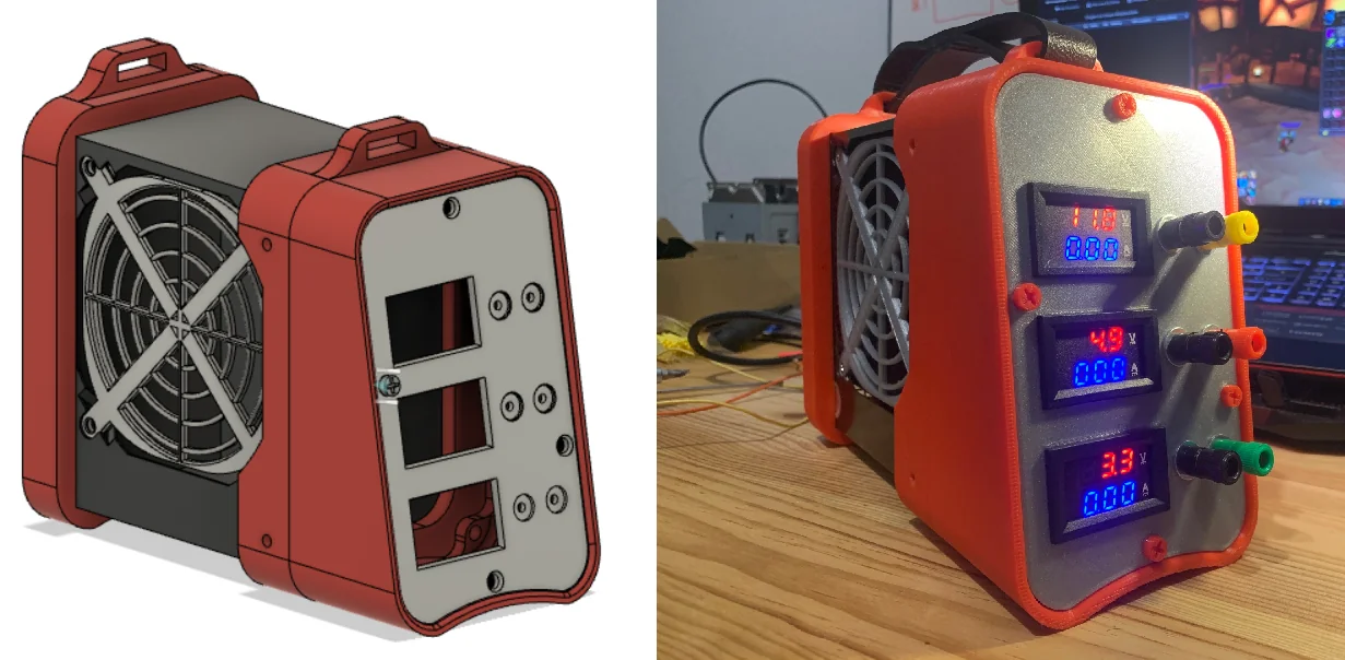 Photo 1.
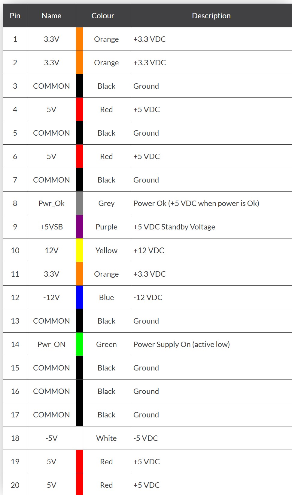
Photo 2.
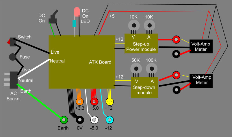
Photo 3.
Back to Top
ATX POWER SUPPLY CONVERSION
by Rob Stokes ZL1RJS
This is my version of the ATX Computer Power Supply conversion. There
are several designs and ways to convert these power supplys. All the
idea's below are taken off the internet. Also take note of my safety
warning.
Please note, Please read my
Disclaimer
and you understand it before
continuing.
Discharge the Capacitors
Proceed with extreme caution.
Look for the biggest capacitors, these can be fairly low in value but
can store high voltages of up to 450v.
To discharge high voltage capacitors, there are a few ways, but I
normally use two microwave light bulbs in series as I find this to be
the best method.
NEVER SHORT OUT any capacitors with a screwdriver. The way I
discharge capacitors is by using a light bulbs, This is much safer and
will not cause any harm but it will quickly discharge the capacitors.
If the capacitor is still holding its charge, by using a light bulb,
you will see the lamp quickly light up and go out. Do this for all the
high voltage capacitors as somtimes there can be more than one.
If you see the light bulb glow, then it has discharged the capacitor
through the bulb and not through you if you were to touch it.
The same will apply if you have powered it on while it is still out of
the case, after it is switched off, you will still need to discharge it
again to reassemble it back into its case. If you don't do this you may
receive a nasty shock.
With faulty PSU's, nine times out of ten, if it does not start up, and
you need to open it up to repair, it will always charge up the mains
capacitors so never assume and always discharge the capacitors.
Trust me... It will bite.
You have been warned, so please be careful.
Also, take note that once you start the conversion of the PSU, it will
no longer be able to be used in a computer again.
Parts List
1x ATX Power Supply
2x LED's (Red and Green)
2x Resistors (330 Ohm)
1x Mini Switch SPST
6x Binding Posts (3 Red and 3 Black)
1x 10 Ohm resistor 10W (Bolt down version)
Optional Extra's
3x Digital Voltmeters / Ammeter (10A Rated)
1x 400W/15A Boost Converter Step-Up (Needed if you want 13.8v output.)
1x 400W/15A Boost Converter Step-down (if you wanted a 9V output.)
3D Case
Let's Begin the Project
There are a number of ways to convert a standard computer ATX power
supply unit into a usable bench top power supply. Depending on what you
want to do, one way is you can buy breakout boards and plug in the
20-pin Molex connector into these boards, or what I have done is to cut
the plug off completely and group together the individual wires keeping
the same colours together, reds to reds, blacks to blacks etc.
You will have around 5 single coloured wires also but I will mention
more on these wires as we go. Depending on the power supply's wattage
will also depend on how many red, yellow, orange and black wires there
are.
Boost Converters
As these power supply's are 12v, you may want to use a boost up to 13.8v
or boost down to 9v
You can do this by using a boost step-up converter for 13.8v and/or
a boost step-down converter to 9v.
If you purchased 2x boost step-up you can put one on the 12v rail to
13.8v and the other on the 5v rail to boost up to 9v. Either will work.
you can purchase these for under $15 each from aliexpress with shipping.
Also using one of these converters, it can be modified as a variable
power supply and with variable current by removing the trim pots off the
boost-up board and running wires to the variable potentiometers using
the same value as the trimpots. These values can vary from different
manufacturers.
I have gone for 3 fixed voltages 13.8v, (I used a boost step-up
converter to boost up to 13.8v) 5v and 3.3v and using the digital
voltmeters, these have a 10A rating.
See Photo 1 for the end result
showing the meters. I also used all red terminal posts, rather than the
coloured terminals as shown. If you are going to use it for transmitting
it is best to have a supply voltage of 13.8 volts, and if you are using
meters you must make sure you do not exceed 10A rating.
Ripple Current
These computer power supplies are known to have a high ripple current
when operating, This can be improved by using a boost step up converter,
which will help to reduce the ripple current. These ATX power supply's
do the job for what I use them for.
3D Case
There are quite a few different designs of cases that you can use or
adapt to your liking.
The 3D case shown in photo 1. was from the internet and this is not my
design. You don't have to re-invent the wheel when a lot of these free
project designs are shared. Thanks Caprageon and to all involved for
their hard work in making this 3D file happen. You can download the STL
files below.
Download to PC the STL Files for 3D Case.
You can say thanks by giving caprageon a tip and help
them continue to share amazing Things with the Thingiverse community.
Check out the link above.
Sorting of the Wires
Once you cut off the connector sort the colours out have access to
the individual wires and soldered them to terminal posts. You don't need
all the red and yellow wires but to maintain a higher amperage output
for both the +5V and +12V supplies, I used 3 to 4 wires of each for red
and yellow.
Seperate all the same coloured wires and join together.
Check the same coloured wires are all coming from the same connections.
Some of the newer ATX12V power supplies may have “voltage sense” wires
that need to be connected to the actual voltage wires for proper
operation.
See photo 2 for the pinouts of the large connector.
In the main power cables you should now have three red wires (+5V) all
connected together and three black wires (0V) connected together as the
others have been used for the LED's and the switch. Also connect
together the three orange wires to give a +3.3V output if you require it
to power smaller devices or micro-controller boards.
If you have only two orange wires, you may have a brown wire instead
which must be connected with the orange’s, the +3.3V for the unit to be
able to power up.
If you only have three red wires, another wire (sometimes pink) must be
connected to the red wires. But check this first.
It sounds quite complex but it really is not. If in doubt check your
model power supply on the internet for pinouts etc, and go from there.
It just depends on how old your power supply is. I am just trying to
cover all the versions out there.
Another tip is, before you cut or remove any wires you can wire it up
first and test it to see if it works and then tidy up by removing the
unwanted wires.
Work out what colours you will use and remove the extra ones.
The colour wires we will be using are:-
Refer to photo 2.
3x Yellow wires = +12V.(one from pin10 and the other two from the power
connectors)
4x Red wires = +5V.
One red wire keep seperate, this will go to the load resistor.
3x Orange wires = +3.3V.(Make sure all 3 are connected together. More on
this below)
7x Black wires = Ground (0V),
We will use four black wires, and the other three wires will be used for
the LED's, switch and load resistor.
Unless you want to use negative 12 and 5 volts, you can remove them.
Unsolder the white and blue wires off the board, or you can also cut the
wires close to the PCB.
White = -5V (Older power supply units only).
Blue = -12V.
The purple wire will go to the red LED using a 330 ohm in series.
If you mount the LED's next to each other the you can use a black wire
for both LED's. If not you will need another black wire.
Purple = +5V Standby (Red LED using a 330 ohm resistor).
The grey wire will go the green LED using a 330 ohm resistor in series.
Grey = power is on (Green LED using a 330 ohm resistor).
The green wire goes to the switch and a black wire the other side.
Green = Power_ON (turn DC on by shorting to ground using a switch).
If you are using 3x meters then use a red and black pair to power up the
meters.
Wiring Up
See photo 3. for the block diagram.
This block diagram should give you enough information to show how to
connect the wires and where everything goes. It is not exactly the same
as the what I have built but shows a good example on what you can do
with these PSU's.
With the step up and down modules, these variable controls may vary in
values with each design, so check the values required if you do want to
make a variable output.
Fitting the terminals to the front panel
If you do not want to go to the expence of meters and a 3d case you can
still use the original case by simply drilling holes on the front of
the case for the terminals. Solder the wires directly onto the posts.
If you want to print a 3D case and add the meters, then you will also
have enougth room to fit the boost converter behind the meters.
Solder each colour of wires directly to the terminal posts for the 12v,
(13.8v) 5v and 3.3v
One other option we have is to use the Grey wire (Pwr_Ok) as a visual
indication that the PSU has started up correctly and is ready to
operate. The Pwr_Ok signal goes high (+5V) when the power supply has
settled down after its initial start up, and all the voltages are within
their proper tolerance ranges. I used a green LED in series with a 330
Ohm resistor connected to ground. This is for the power LED but anything
similar will do, its only indication to show it's on.
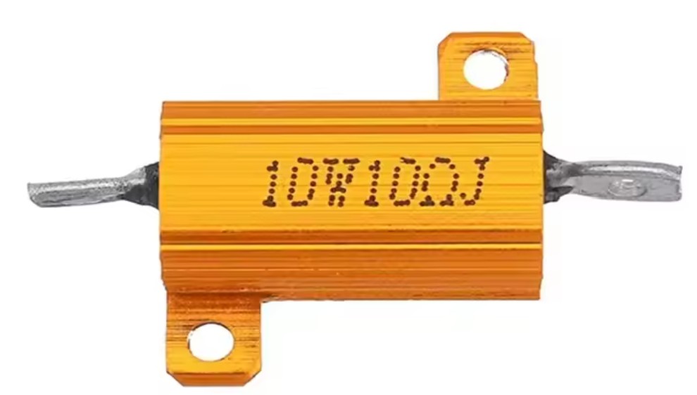
Load Resistor
Next we need to provide a small load on the +5V (red wires) output to
trick the PSU into thinking its attached to the motherboard and to keep
the power supply in the “ON” mode. To do this we have to connect a large
resistor of 10 Ohms, with a standard power rating of 10W across the +5V
output using just one set of the red and black wires.
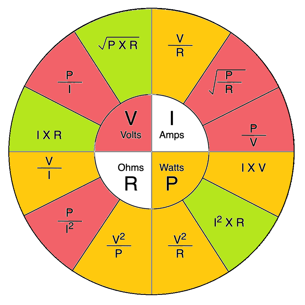
Remembering Ohms Law that the power (P), developed in a resistor is
given by the equation of: P = I² × R or P = V² / R, where: P = power
developed in the resistor in watts (W), I = current through the resistor
in amps (A), R = resistance of the resistor in ohms (ohm) and V =
voltage across the resistor in volts (V). The voltage will be +5V and
the power required is 5W or above.
I recommend you use a 10 ohm, 10W resistor. If you use a lower resistance
than 10 ohms, the power supply you may get low voltages like 8.2v for
the 12v rail.
Using a higher resistance over 10 ohms, then the power supply may not
start up and remember that this resistor will also get HOT! so make sure
it's out of the way of any wires.
By Using a 10 Ohm resistor, this
works perfectly.
This resistor is only used to trick the PSU on by loading the power
supply. If you have to buy this resistor try and get one that can bolt
to the case like the one below or similar.
Description in more detail
To start up a stand alone PSU for either testing purposes or as a bench
power supply, we need to short together the Green (Power-ON) to one
of the common black wires (ground) which is how the motherboard tells
the power supply to turn “ON”. Use a black wire and connect a switch
to the green Power_On signal and Ground. This means when the green wire
is momentarily or permanently connected to ground the power supply will
turn-ON.
Final Testing
Testing the Power Supply
Once fully assembled you should end up like the picture on the right
hand side of photo 1. It also shows it is not quite 12v so if you get a
volt meter to calibrate, check the voltage and adjust the trim pot to
the correct voltage if necessary, but be careful if you do this, as you
can damage the tiny trim pot.
I mounted the DC on and stand-by LED's above the meters and on the same
line, the DC on switch, centered above the output terminals.
I hope you enjoy and have fun building this project.
73 de Rob
© 2024 ~ ZL1RJS