VHF - UHF Diplexer
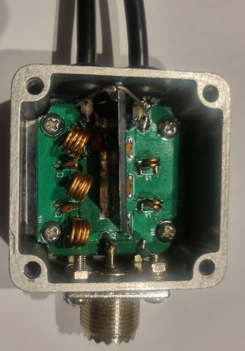
Photo 1. Prototype
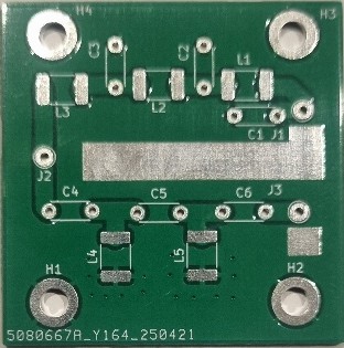
Photo 2.
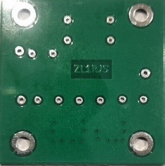
Photo 3.
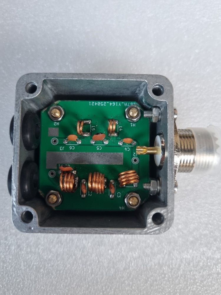
Photo 4.
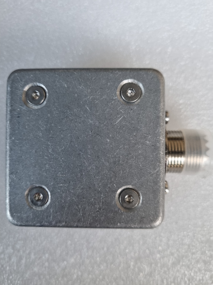
Photo 5.
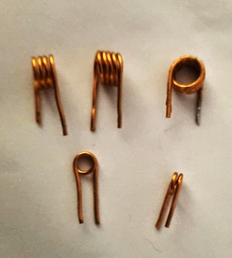
Photo 6.
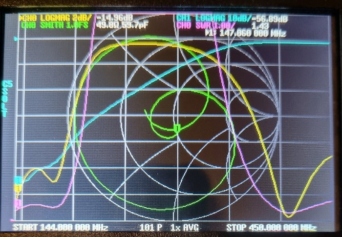
Photo 7.
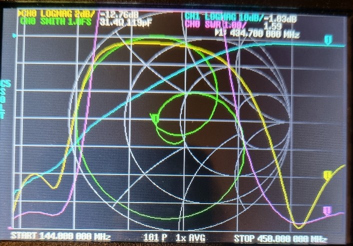
Photo 8.
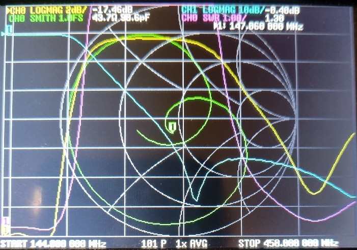
Photo 9.
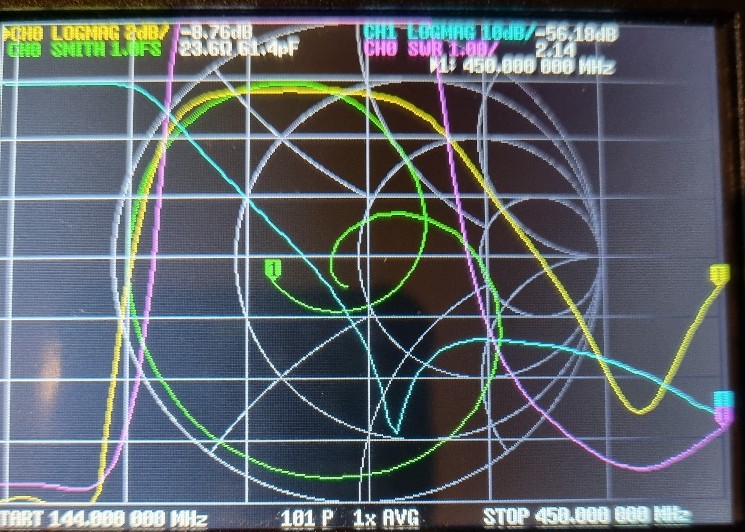
Photo 10.
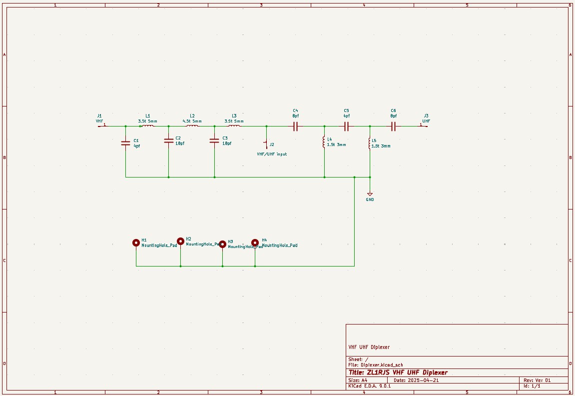
Schematic diagram Diplexer
Click on the image above or here to enlarge
Photo 11. Schematic Diagram
Back to Top
Schematic diagram Diplexer
Click on the image above or here to enlarge
Photo 11. Schematic Diagram
Back to TopVHF - UHF DIPLEXER Project
by Rob Stokes ZL1RJS
This is my version of the VHF / UHF diplexer.
Please note, Please read my
Disclaimer
and you understand it before
continuing.
Tools Required to Build This Project
Soldering Iron (Temperture Controlled)
60/40 Tin/Lead Solder
Craft Knife or Needle File to scrape away the enameled coating on the
coils.
Philips Screwdriver
1.5mm hex wrench
5mm box spanner or you can use pliers
Long Nose Pliers
Side Cutters
Tweezers
Parts List
2x 18pf Capacitors C2, C3
2x 4pf Capacitors C1, C5
2x 8pf Capactors C4, C6
1x 4.5t 5mm Coil (L2)(Made from 1mm Enameled Copper Winding Wire)
2x 3.5t 5mm Coil (L1, L3)(Made from 1mm Enameled Copper Wire)
2x 1.5t 3mm Coil (L4, L5)(Made from 1mm Enameled Copper Wire)
1x Diplexer PCB
1x 15mm x 32mm Blank Double or Single sided PCB (For screening)
1x 5cm x 5cm x3cm Aluminium Enclosure Diecast Box
1x UHF SO239 Female Jack 2 Hole Socket
1x BNC to BNC RG58 lead 60cm (Cut in half) to fit Tait Radios
Or
60cm of RG58 cable. (See optional parts list)
4x 10mm Stand-off M3
4x M3 Nuts (To hold the PCB board)
4x M3 6mm Countersunk bolts
2x 1/4" x 1/2" Rubber grommets
2x Nuts and Bolts + spring washers for the UHF SO239 socket
1x Lug terminal (To earth the socket to the PCB) See Notes below to
fit this part.
1x 4cm wire (For connecting the shields/earths of the RG58 together)
Optional Parts List
If you are not using the BNC cables, then make you own leads to suit
your radio, using your choice of
N type or PL259 Plugs.
1x 5mm Bolt (To make the coils)
1x 3mm Bolt (To make the coils)
Let's Begin the Project
Making of the Coils
These have been ready made for you in the kits, but this is how I made
them.
You are going to need approximately 400mm in total of enameled copper
wire to make the coils. There are two sizes of the coils that we need to
make.
Three coils are made with a 5mm air gap and the other two are made with
a 3mm air gap.
See photo 4. The top 2 coils L4 and L5 were wound on the 3mm bolt and
the bottom 3 coils L1, L2 and L3 were wound on the 5mm bolt.
To make the coils, use a 1mm Enameled Copper Wire.
First, make the coil for L2. Start winding the wire tightly around a 5mm
bolt.
Using the 5mm bolt, hold the head of the bolt in your left hand.
Place the wire behind the bolt. Leave a start tail around 10mm and start
to wind the wire over the bolt, turning anti-clockwise 4.5 turns around
the bolt and stop.
End with a 10mm tail and cut the wire.
Photo 4. L2 is the middle coil bottom of picture.
Photo 6. shows the picture of all the coils made.
Make sure to leave enough tail wire to make the connection to the board.
After the coil is wound, using a craft knife or a small file, scrape away
the enameled coating off each end of the coils to expose the copper wire.
This will allow the copper wire to be soldered to.
It may be easier to scrape the coating off while it is still on the bolt.
To get the coil now made off the bolt, unscrew the bolt from the coil.
Once you have made 1 coil the rest will be a lot easier to do.
You need to make 2 more coils but now with 3.5 turns, still using the
5mm bolt and using the same method as above.
Next, make the last 2 coils L4, L5, except now wind the coil around the
3mm bolt, for these coils you only need 1.5 turns.
Use the same method as you did above for the L2 coil.
Solder the Coils to the PCB
These coils are not through hole on the board, so you will need to bend
each of the legs of the coil at right angles so they can be fitted to
the board.
Once all the coils are made and shaped, trim the coil to fit the pad,
but before fiting to the PCB, tin each of the ends of the coils with
your soldering iron.
On the PCB, tin ONLY one side of the coils pad circuit board first with
solder, fit the coil onto the board. You may need to use tweezers to
hold the coil as it will get very hot. Holding the coil in place, heat
the pad you just tinned to make connection. Once the coil is soldered
on the one side, solder the other side of the coil to the pad on the
circuit board.
I am not sure if it makes a difference on which way round the coils go,
but I fitted all the coils in the same way as the coils are wound. All
coils are Anti-clockwise wound so I started with the 5mm coils first at
the SO239 end, J2. Fit L3 (4 turns) and the start tail went on J2 and
making sure the next coil L2, (5 turns) was also anti-clockwise and
the start tail joined onto L3, C3. Fit L1,the last 5mm coil with
(4 turns) anti-clockwise so the start tail joins C2, L2.
With the two 3mm coils, these were also fitted with the winding in the
same direction.
TIP
As the coils will get hot when soldering, by using tweezers or
equivalent should make it easier when fitting these coils to the PCB.
Capacitors
Fit the capacitor's to the PCB. There are 6 capacitors in total to fit.
Sort the 3 values together, 2x18pf (C2, C3), 2x8pf (C4, C6) and 2x4pf
(C1, C5). fit the same value capacitors on to the PCB as not to mix them
up.
Screen divider
I added a blank copper clad board onto the PCB as a screen divider to
keep the RF away from the UHF/VHF signals. Once you have fitted the
coils and capacitors, cut the corner at the top of the screen divider
and then fit this screen divider to the PCB. Make sure it is fitted in
the right place before to solder to the PCB. The cutout is to allow the
4cm wire to bridge over and connect the earths of the coax together.
This is also mentioned a bit further down.
Drilling the holes in the case
I have pre-drilled all the holes for you in this kit, but this is how
it was done.
Drill a 14mm hole for the SO239 socket on the side of the case.
Drill 2 x 10mm holes to fit the gromments on the opposite side.
The gromments I used were 1/4" x 1/2".
Drill the hole size to suit
the gromments you are fitting.
Open the enclosure there is 33.2mm inside edge between the hole pillars.
Measure and mark the center 16.6mm. Measure down 10.5mm on the 16.6mm
line and mark.Drill the 14mm hole. I used a stepper drill to drill 14mm.
After drilling the hole, continue with the 16mm very slightly, just to
countersink the hole as the SO239 socket has an tapered edge slightly
bigger than 14mm, continue until it is flush with the case.
On the opposite side, mark the center again of 16.6mm. Next measure
7.5mm from the center and draw a line. Do the same the other side from
the center. Measure 9mm and draw a line. Measure 9mm down on each line
and mark. Drill 2 x 10mm holes. Fit the grommets, one to each hole.
Do not fit the SO239 socket yet.
Before fitting the PCB and inside the case, fit the BNC leads. Follow
the next step on "BNC Leads" as it will be easier to fit the BNC leads
first onto the PCB board while the PCB board is outside of the case.
Fit the 4cm wire to bridge the two braids together, and also
solder the wire to the top of the copper of the screen divider.
You may need to cut the corner at the top of the divider to allow the
case lid to close and for the wire to go over the screen divider. You
will not need all the 4cm wire, the offcut you can use to solder a wire
onto J2 ready to connect to the SO239 socket.
BNC Leads
Without having to put a BNC plug on each of the cables, I went for a
ready made BNC to BNC lead as this was easier and a cheaper option.
First, cut the BNC lead in half. Trim back the coax, when cutting and
stripping the ends, make sure you do not pull the center cable when
stripping, otherwise you may pull the center pin out of the BNC plug.
Tip
After stripping the cable back, check each BNC plug that the center pin
is ok and has not been pulled out.
If you have pulled the pin back, you will need to push the center back
up the cable until you can get hold of the center pin of the BNC using
some long nose pliers to pull back into place. This is easier to correct
now than later once it is has all been assembled
Fit the
grommets to the dicast box and push the coax through each grommet to
join onto the PCB. Allow the leads to be pushed through the gromments,
giving you more room to solder the leads onto the PCB. Once they are
soldered, you need to push the leads back through the gromments, so the
PCB will locate on the spacers to fit the nuts. The leads are not inline
to the PCB which will make the lead a bit harder once assembled if you
were to accidently pull on the cables.
Fitting the PCB 10mm Spacers to the Case
This has all been pre-drilled ready in the kit and again how I did it.
Cut the corners off the PCB to make it fit into the case. Get the PCB
around the correct way first so that the PCB lines up with the SO239
socket and the otherside with the two cables. Next use a marker pen to
mark the 4 x holes to drill. Remove the PCB and Drill 4 x 3mm holes.
Once the holes are drilled, turn over the case and countersink the 4
holes using a countersink drill until flush to the case. See Photo 5.
Fit the 10mm spacers to the PCB first and loosly tighten.
This will make it easier to get the PCB board back into the case.
Fit the countersink screws so you are ready to tighten up.
Once the PCB board is in place, tighten the hex bolts and tighten
the nuts.
SO239 Socket
Once you have fitted the PCB and tightened down in the case, fit the
SO239 socket. It has two mounting holes. The proto-type in photo 1 used
a SO239 socket with four nuts and bolts, but was changed for the two
hole socket which made it easier. The two Nuts and bolts supplied came
complete with a washer and a spring washer. You will not need the washer
as it will not fit, but you can use the spring washer when fitting this
socket to the case. The offcut wire should be soldered to J2 on the PCB,
solder and connect up to the center pin of the SO239 socket.
Earth Lug
A few of these kits have now been built and tested without fitting
the earth lug, as the PCB is earthed to the case through the brass
standoffs. The original prototype did not use brass standoffs.
You can leave off fitting this earth lug for now or fit if you want to
make sure it is earthed.
Fit the earth lug on the UHF side to the SO239 socket. To fit this lug,
you will also need to scratch away the paint to solder the lug to the
PCB board. The lug may also need to be cut on one side of its edge as
the case pillars may prevent it from being flat, so cut one edge off the
lug so it will fit into the inside of the case.
It can be a challenge to fit the nut and bolts.
TIP
A magnetic screwdriver comes in handy to help place the spring washer
and nut in place.
Once you have tightened up the SO239 socket. fit and solder the wire
from J2 to the center pin of the SO239 socket.
The Diplexer should now all be complete and ready to test. Fit the lid
to test.
If any adjustments of the coils are required, always re-fit the
top cover to carry out tests.
Tuning the Diplexer
You MUST terminate the other side of the diplexer first with a 50
ohm dummy load when checking the measurments with a VNA or Spectrum
Analiser.
If you are measuring the VHF side of the diplexer then you put the 50 ohm
dummy load on the UHF lead, and vice versa, so when measuring the UHF
side, you put the dummy load on the VHF lead.
Failure to use a dummy load will give false reading.
When doing any measurements, it must be in it's case.
See photos 5, 6, 7 and 8. The blue line shows the waveforms cutoffs.
When I build this proto-type diplexer, I found the waveforms were not
quite right and doing further tests, I had to earth both sides of the
cables where the VHF and UHF cables come into the case. I used a small
4cm piece of wire to join both shields together and also soldered the
top of the wire to the screen divider where it crossed over.
After this was done it reduced the waveform for the cut-off on the VHF
side. On the VNA it changed from -33.64dB to -62.32dB by adding this
wire. The UHF side had no problem.
Completed Diplexer
Once fully assembled you should end up like the picture of photo 1.
Credits
A special thanks to Keith ZL1BQE for showing me tips on Kicad on how to
design, size the printed circuit board and tips on making this project
possible.
I hope you enjoy and have fun building this project.
73 de Rob
© 2024 ~ ZL1RJS