
ALLSTAR RADIO
PROJECT
by Rob Stokes ZL1RJS
This Allstar Radio Project remote base station is my version, how to
build using the latest version software, using a Baofeng BF888S radio
, USB fob and a raspberry pi, plus how to install and program to get you
up and running on Allstar.
To use AllStar, you will first need to register to get a node number.
Below are the details on how to build, and register with AllStar to get
your node number.
Credit goes to all the Allstar designers. There are several designs and
different versions out there to build being open sourced.
This is the version that I have built. It works very well and is cheap
to build.
The hardest part is to modify the USB fob and solder three wires to the
48 pin smd IC. I do still have a few of these fob's left already fully
assembled, if you don't feel comfortable with soldering.
I have these USB fob kits at $30 (parts included are below)
Email.
You can contact me directly via email on
ZL1RJS
Just click on my callsign to email your interest.
Please note, I take no credit for the design and please read my
Disclaimer
and you understand it before
continuing.
Description of This Project:
AllStarLink is a network of Amateur Radio repeaters, remote base
stations and hot spots accessible to each other via Voice over Internet
Protocol. AllStarLink runs on a dedicated computer (using the
Rasperry Pi) that you host at your home or radio site.
It is based on the open source Asterisk software which makes Asterisk a
powerful system capable of controlling one or more radios. It provides
linking of these radio's called "nodes" to other systems of similar
construction anywhere in the world via VoIP.
AllStarLink's primary use is, as a dedicated computer node wired to your
repeater or radio. Connections from Echolink and other VoIP clients are
also supported.
The Allstar network is like Echolink but is way more powerful over
Echolink with more features etc, and you can use both Allstar and
Echolink systems together.
FIRST Sign Up To Allstar and create an Account.
Before you start construction, it is best to register first with Allstar
as this registration process can take 24 hours to do.
To use AllStarLink you must be an Amateur Radio operator with a current
license. This is because AllStarLink is a network of ham radio stations
which only hams may transmit on. Allstar use QRZ or other public
databases to check the information you provide. If you are not listed in
any publicly accessible database they will ask you to email a copy of
your license.
Once you click on to Allstar's main page to register, you will need to
click on "Login/Sign-Up" at the top of the page.
Allstar Registration
Here.
Once you have completed the form and signed up, you will receive an
email with a link to confirm your email address.
Watch for that email and also check your junk folder. You should get it
fairly quickly. By adding
"helpdesk@allstarlink.org"
to your contacts list should prevent any
emails going to your junk folder.
Once you receive this email, you must click on the link to verify your
email address, before you will see your account request.
Only then will Allstar be able to verify your callsign.
After they verify your call sign and information (usually within 24
hours) you will receive an email with your account.
Once you receive your login, login and request a node number.
Click on "Portal" and " Node Setting" Here you can request a node number.
NOTE: You CAN NOT login to your AllStar Link account until your email
address has been verified (by clicking on the link they send)
Also if you don't have Echolink, as with Allstar you will need to
register first, before you can use it. On my "Links" page you will find
the necessary link.
More infomation can be found here
Wiki Information Page for AllStarLink
There are lots of information and plenty to read on Wiki.
WARNING TO IMPORT RADIO TRANSMITTERS.
Please be aware that importing radio transmitters like Baofeng, and
other brand names into New Zealand requires a licence to import these
type radio's and details are recorded to whom they are sold to, along
with serial numbers etc, to the RSM (Radio Spectrum Mangement) as a
requirement by them.
I do have a licence to import radio's if you require one and I will only
import to order.
That said all the Baofeng BF888S models that I have seen DO NOT have any
serial number marking, so any radio found without any serial numbers.
I will engrave a identifing number on any that I sell to comply with RSM
requirements.
If you try to import radio transmitters without a import licence, they
will be intercepted at customs and get confiscated, so please be aware!
It is also illegal to operate these radios outside of the Amateur Radio
bands. I will also only supply to a licenced amateur with a valid
callsign. The Radio will also be programmed for amateur frequencies only.
Materials Required.
Required Hardware.
- A fully assembled FOB.
- A Raspberry Pi3, Pi4 or the latest Pi5.
- A case for the Raspberry Pi and radio. A metal case is preferred
but if you want to use a Wi-Fi connection instead of a wired network
connection then a plastic case may be required to obtain adequate
range. I built mine in a old DVD recorder case
- A microSD card – 16GB or larger, Class 10 or better.
- A power supply for the Pi – This should be a power supply intended
for your version of the Raspberry Pi. These supplies typically provide
5.1 to 5.2 VDC to the Pi. Current requirements vary with version of pi.
Numerous problems with Allstar Nodes have been traced to inadequate
power supplies.
- Baofeng BF888S Radio (16Channel UHF Only)(or equivalent)
- On/Off Switch SPST Master switch.
- Optional extras.
- If a wired network connection is used then an
external RJ45 chassis mount extention lead
- Raspberry Pi 5v Fan(See Notes if you add a fan)
- SMA Right angle for radio antenna
(The Raspberry Pi and radio, plus case and switch are not included in
the kit)
FOB Kit Includes.
- 1x USB FOB (Modified ready).
- 2x Buck converters. (1 for the pi and the other for the radio).
- Led's 1x Red, 1x Amber, 1x Green, 1x Blue/Red.
- Resistors, 470R, 390R, 2x 10K, 100R, +/-18k
- Connection wires (Approx 10 to 20cm long).
Power Up the Pi.
Depending what power supply you use, make sure it is able to supply
enough current for your pi. This is very important as it can
cause issues when in use. I used a 12v 3A as this was what I had on hand
at the time. This was enough to power up the radio and the pi 3.
When you connect up the raspberry pi, I used another buck converter to
power up the pi, I made sure that the voltage was 5v before the
connection was made to the pi.
I also connected and soldered the power 5v underneath (see photo 3.)
Negative to PP3 and Positive to PP1
When this node was made, back in 2016, I used a Pi 3b 2015 shown in
photo 3.
I have just noticed that depending on which year the Pi was manufactured
the layout is different for the later Pi's so please beaware of this as
Photo 3 is only for the 2015 year of manufacture.
If you do solder directly to the PCB, then pay attention to the correct
pads.
Another idea is to cut up an old lead to power up the pi. I have cut
back the outer of the lead exposing the red and black leads going to the
buck converter.
Warning
Make sure you connect the powers polarity correct as it will do damage
if it is connected wrong.
I take no responsibility for any damage,
so please be careful.
I was also sent this photo to me some time back, so no idea of ownership
of who or where this photo originated from.
Great photo showing connections. I originally powered up the pi and
connected up using the header pins but was told not to do this, as it is
5v out, so I quickly modified mine. I tinned the copper pad first before
soldering the wires to the pi.
UPDATE Jan 2026.
A couple of new hams from my local club are currently building up nodes,
using the same way I built my node. I have since done a couple of new
modifications, where as I was missing calls when the station connected.
I now have 4 LED's, A Power LED which is taken the supply from the output
header pins 5v rather just from the 5v feed.
This LED now lights up indicating when the Pi is powered up.
The yellow heartbeat LED has not changed.
I added a Rx LED and changed that to Green. The wire that comes off Pad
7 (brown wire) of the USB FOB now goes to the red LED. (not Green)
Doing this mod, now means I do not miss a call when a station connects.
I have also connected the green LED directly on the radio's Rx (green
LED). I disconnected the feed resistor (just lifted up one end of the resistor
in the air) to stop the green LED on the radio from working and fitted
the external Green LED still using a 470R Resistor. I disconnected this
resistor and LED as not to put any stress on the circuit.
On the Baofeng BF888 I followed the resistors track back to a better
point to solder the wire (Anode wire) to. The TX and RX LED's are
located just by the Volume control. the feed resistor is just to the
right. I fitted the Anode wire folling the track down slightly and just
above the mounting screw.
Just be aware that there are different
versions of these radios so the layout may be different. Just follow the
track with a meter to confirm you have the right tracks.
Looking at the radio with the antenna top left, The transistor should be
on the left of the LED and the tiny resistor is to the right of the LED.
The cathode connection is on the small transistor next to the radios
green LED.
Lower down mentions about a white LED for Rx, I made my LED green but
you will need to follow the instructions to enable the Rx LED and I
found it easier just to modify the radio for the same result.
The other mod that I thought of was to use a 5v supply using the later
Raspberry pi 5 power supply being rated at 5A and cheap to buy. This
will NOT work as the power supply has current sense, and I have added
this info just incase you may think to use one.
You can however use a Pi 4 power supply, which is 5v and rated at 3A.
You can use either power source, but if you use 12v in, you still need
to use the Pi's buck converter 12v in down to 5v to power up the Pi.
Connect the Radio's buck converter's to the output of the Pi's buck
converter 5v. Set the radio's buck voltage 5v in down to 3.7v
Set the voltages BEFORE you connect these to the Pi or the Radio.
NOTE: The USB FOB modification lower down will need to be changed and
updated. I will update this when I can. Please be aware when you get to
this mod's instructions, the above, is now what has changed.
The wire I used for the LED's was from a off cut of cat 6 cable.
Colours used are:
Blue LED: Anode connects to Resistor and Blue wire.
Green LED: Anode connect to resistor and Green wire.
Green LED: Cathode connect Green/White
Yellow LED: Anode to resistor and orange wire.
Red LED: Anode connect to resistor and Brown wire
All the cathodes for Blue, Yellow and Red LEDs are connected together
using the Blue/White wire connected to the Pi's ground.
FAN UPDATE Jan 2026.
If you want to add a fan, I suggest using either a PWM fan or a standard
5v using a speed control as just the standard 5v fan gets quite noisy as
it is running at full speed.
ALLSTAR REGISTRATION.
If you have not yet applied for a node mumber, register and apply now.
click on "Login/Sign-Up" at the top of the page.
Allstar Registration
Here.
Once you have applied for a node number, you need to get the password of
your node number. To find your node's password, Go to the AllStarLink
webpage.
login to allstarlink.org
Click on the link below and "Login/Sign Up" and enter your Callign and Password. Click
"Login"
You should see your callsign at the top.
Click on "Portal" to the left of your callsign and click on Node Setting.
This will show you node number. Under Password click on "Show" to reveal
your password. Take a note of the password as you will need this later
on in the set up.
You can now close out and exit Allstar.
Lets get Started with the Construction.
Case
I found an old DVD player but removed everything just for the case which
had already had a hole at the back for a RJ45 Lan connector and a USB
socket at the front. I modified the DVD's existing front PCB board and
cut it nearly in half but leaving enough of the PCB still to use the
existing mounting holes and tact switches, so I could make use of this
USB socket and switches. I removed any components off the board which
just left the USB socket and tact switches.
As the raspberry pi will be mounted in the case, I used a USB extension
lead which one end would plug into the pi and I cut the other end off
and wired up the other side to the PCB. You don't have to do this but if
you needed to use a USB port for anything like, e.g. USB wireless
keyboard or a external USB Wi-Fi module, it is easy accessed from the
front case.
The edges of these cases can be VERY sharp and to avoid any cuts, I put
some electrical tape over the full length of each side to stop any nasty
cuts. I mounted the radio on the left and the raspberry pi in the middle
leaving enough room for the USB Fob. The buck converter for the radio
was mounted close to the radio. The same for the Pi.
I just had enough room when I installed the pi (shown in the photo 2.)
It is also quite hard to get to the microSD card and I have to remove
the fan for access. If I made another I would advise to mount it
sideways. This will also mean shorter wires.
As this does not need a monitor, I used the buttons from the
case to shut the pi down as it is not good practice just to switch off
as this can corrupt the pi. With the later version of supermon, you
don't need to do this now as the new version is command driven, so less
to do in the construction. More said on this later.
If you have access to a 3d printer you can always print off a case but
you will need to either design one or find a suitable case from the 3d
library's.
Baofeng Radio.
Before you modify your radio, it will be easier to program the radio
first. You will need a programming cable to do this.
Programming Cable
Here is a link for one on Amazon, but I do not know how long this link
will work for.
Just make sure before you buy one, it will work with your
computer's operating system.
Check out local first or ali-express to get a cable, but make sure you
get one that works with the latest version of windows or linux.
Some cables only work on XP which is no longer supported and no longer
works.
I found Chirp is the best program to use, you can download this here.
Download Chirp
Download and install the latest version.
Install process, Chirp setup
Agree to the licence, "I agree" click next
Choose the directory, just agree to selected path and click install.
Click "finish" this will open up the chirp program.
First time users click on "agree"
If Chirp is not maximized, then maximize the screen to see all the full
list of setting.
Next click on "radio" and select "download from radio"
Choose your radio from the drop down windows.
Port: "your com port"
(NOTE: You should see the port number to select.)
Vendor: "Baofeng"
Model: "BF888S"
(If it comes up with any error, then check your drivers as the USB
programming cable may not be compatible)
You should see the green light flickering on the radio as it reads the
memory.
I normally take a blank original copy of the radios config and save it.
Then I make a copy and modify the copy.
If you own more radio's of the same model, BECARFUL, if you upload a
wrong config file that is not from the original model, you can "brick"
the radio and it's game over.
NOTE:
It's best to read and download the radio's memory first, save a copy,
then modify the copy keeping the original config file un-edited.
If you make a mistake you always have a back-up.
Radios having the same model number can look the same, but can have
different firmware, and version numbers that are not interchangeable.
You have been warned...
Once the config file is displayed,
In "Memories"
You may see that you have unwanted frequencies, you can edit the line
and modify the frequency or delete the line and enter your frequency you
wish to use.
Set your transmit power to low as you do not need high power.
You can also set a CTSS tone if you wish to stop any interference from
anything local. Remember if you do use a CTSS tone to program your main
radio that you will also be using with the same CTSS tone.
Go into the setting tab and un-tick all the ticks as none of these
functions are not used, and on the timeout setting, set to "off", it may
be currently set to "180" seconds. You are now done and ready to upload
the config file.
Up the top, click on"radio"
Select "Upload to radio" to program.
It should flicker again green, indicating it is receiving the file.
Once programmed, save the new config file, exit the program.
Now proceed and click on the link to modify the radio.
The link below is my version of the BF888S radio and there are quite a
few different version radios depending on the age of your radio, Follow
the instructions for the step by step installation and see the next link
ONLY if your radio is different.
Modifing the Baofeng BF888S
Use this link below ONLY if your BF888S is different to the one shown .
You will need to see which version you have, and show you where you need
to connect the wires to your version. Still follow the rest of the
instructions on the above link as these are the main notes and ONLY use
the link below to show how to connect the wires to the different radio
versions.
Different Versions of the Baofeng BF888S
Different Radios used for AllStar.
The link below has more information on using different radios to modify
and other technical information, tips and it is full of information.
I have added this link for interest. Take a read when you can.
Hamvoip
Building the USB FOB
Building the USB FOB
This link above will show you how to build the USB FOB.
Once you have completed all the construction side above and ready to
turn on, then proceed to the Software Installation below.
SOFTWARE INSTALLATION.
In this section you will obtain and download the Allstar Image file,
plus the Raspberry Pi Imager program which is required to burn the
image file, and prepare a microSD card which you will plug
into your Raspberry Pi once done.
These instructions assume you will be using a Windows PC. The process
can be completed using an Apple Mac or Linux PC also, but you on your
own with those operating systems.
Raspberry Pi Imager Installation.
Update 01-06-2026
NOTE: Please read my notes below when installing Raspberry Pi Imager.
If you download the latest Raspberry Pi Imager file, be aware of these
version's, the version's below 1.95 verses the latest versions above
2.0.0 have a different set-up procedure.
For Version's below v2.0.0 follow these steps below but for the latest
version scroll down for the latest set of instructions...
Ver1.85
You need to be able to modify the Allstar image to change and put in
some details.
Details required are:
Your node number and user name (Put your callsign for the user name)
plus password and your wi-fi setting etc before you burn the image to
the microSD card.
(I used an older version v1.8.5 to do this, please see the link below
for v1.85).
I have included version 1.85 which works well and is what i used to
program the image file. When you install this version, it want's to
update the program when you open it. For now select "NO" and follow the
prompts.
Download Raspberry Pi Imager 1.85 for windows to PC.
Download the latest AllStarLink 3 image for the raspberry pi from
AllStarLink 3 Image
or here
AllStarLink 3 Images
For different versions.
Info on AllStar Link, user guide online.
Online AllStarLink3 Manual
Let's Begin with the Raspberry Pi Imager Installation.
Once downloaded, Click on and open Raspberry Pi Imager
Do not update the program at this stage (if Prompted)
NOTE:
Before you start to burn the image to the micro SD card, you will need
to have on hand, your node number and your Network's SSID name plus
password. We need to add this information before you burn the image
file.
You need to first set-up 3 things to burn the image.
Raspberry Pi Device.
Operating System.
Storage.
scroll down or read down to step by step Pi Appliance Set-up
- If you have not already installed then install Raspberry Pi Imager
1.85 on the link above.
- Download the latest release image (click on this link above)
This will be named allstar3.arm64.x.y.z.img (where x.y.z. is
the latest version. Save it to your local downloads directory.)
- Launch Raspberry Imager DO NOT INSTALL UPDATES
- Choose device
- Choose operating system OS - scroll to bottom of list and "Use
Custom"
- Select image - now navigate to the download folder and select the
image allstar3.arm64.x.y.z.
- Next choose storage, mass storage 16Gb USB device or your USB
device. - This is your microSD card where the allstar image file will be
- Click "next" - as we have to set some setting.
- This next bit is Important... Click on "edit setting"
- Set hostname, example "node45481" (where node45481 enter your node
number in place of mine).
- Set Username and Password. I used my callsign as the username
(lowercase) Choose your password (Password will be case sensitive)
(and record your username and password somewhere safe as you will
need this later, when you go to login to the landing page).
- Tick box to set "locale setting"
- Optional Wireless - You dont have to set this if you are not using
wireless, otherwise "configure the wireless LAN" by entering the
SSID and wi-fi Password of your router.
- Click on "Services" and make sure you enable the SSH check-box
Use password authentication. Next click "Save" then click on "YES"
This will now write to your microSD card.
Remove the SD card and you should now have sucessfully created the image
file ready to boot-up. Install the microSD card into the pi.
Before you turn on the pi, continue to Configuring the Pi for AllStarLink
Ver 3.
Ver2.0.7
To get the latest version of the Raspberry Pi Imager on the link below.
Latest Raspberry Pi Software
After downloading the latest current version, run the Raspberry Pi
Imager file and follow these steps. These are different...
- If you have not already installed the latest program, then install
the Raspberry Pi Imager program on the link above.
- Launch Raspberry Imager v2.0.7 (or later) Update to the latest
version (If Prompted)
- Click on "APP OPTIONS" (Located in the bottom left corner)
- Now click on "EDIT" (Content Repository)
- Click on "USE CUSTOM URL"
- Click on this link below to copy the URL address to get the image
file.
AllStarLink 3 Images
This opens up a new window. Select the image file you want to install.
- Scroll down and right click your mouse on the image file
rpi-imager-os-list.json and copy this link address to select
this file.
- Close this window and go back to the Pi Imager program and paste the
link in.
- Press " APPLY AND RESTART"
- Choose your device e.g. Raspberry Pi3 (Select the version pi you
are using.) Click "NEXT"
- Select the image file selected AllStarLink 3.2.0 (Trixie)
This is the latest version out in May 2026. Click "NEXT"
- Next choose storage device, mass storage 16Gb USB device or your USB
device. - This is your microSD card where the allstar image file will
be. Click "NEXT"
- Now enter your Node Number, example "node45481" (where node45481
you would enter your node number in place of mine). Click "NEXT"
- Next put in your City (e.g. Wellington, New Zealand.) Click "NEXT"
- Put in your "TIME ZONE" and "KB LAYOUT" (e.g US) Click "NEXT"
- Set Username and Password. I used my callsign as the username
(lowercase) Choose your password (Password will be case sensitive)
(and record your username and password somewhere safe as you will
need this later, when you go to login to the landing page).
- Optional Wireless - You dont have to set this if you are not using
wireless, otherwise "configure the wireless LAN" by entering the
SSID and wi-fi Password of your router.
- Enable "SSH" and "USE PASSWORD AUTHENTICATION" Click "NEXT"
- This now will show a summary of what you have just entered, click
"WRITE" Once you have done this it will confirm that you are about to
erase ALL DATA. Click on "I UNDERSTAND and WRITE."
- This will now start writing to your microSD card.
Remove the SD card once finished and you should now have sucessfully
created the image file ready to boot-up. Install the microSD card into
the pi.
NOTE:
Once you boot up for the first time it takes approximately 30 or so
minutes, so allow this time for all the updates to complete.
Configuring the pi for AllStarLink Ver 3.
Your AllStar node should now be all built and complete before you
continue these next steps...
Now, you are ready to power up for the first time.
I have put together this install guide below with trouble shooting with
2 issues, I had with one of the node units that had just been built.
Hopefully this will help you with the installation.
AllStar ASL3 Installation Manual
Thanks again to the Ham Radio Crusader, Freddie Mac KD5FMU
Follow this step by step YouTube video below on setting up Allmon ASL
ver3.
I do recommend you to watch each step first, and then go back to follow
his steps, pausing each step to keep up with Freddie.
Watch the youTube Tutorial Video here.
AllStarLink ASL Version 3
Update 16-03-2026 - I have now added my installation manual with config
files as a comparison for anyone who has built this allstar project.
This will include all the setting that I have used when setting up that
freddie covers. This should give you an idea for the setting as these
nodes have all been built in the same way.
Freddie does cover all the commands but it will vary depending on how
you want to set yours up. For a basic node just follow freddie's
setting. When you are in the setup menu and get to Number 8. "Interface
Tune CLI", you will need to also change in menu J needs to set as "No"
for the radio to work, (currently set as usbinvert).
TIP
When changing any .conf or .ini or other script files to make sure you
back up your files first. If you clone your SD card before any changes
so if you were to make a mistake then you can revert back to the back up
otherwise you may have to re-install AllStar all over again.
APRS - To configure your node to show your AllStar node up on
the APRS network, click on the link below for instructions.
Configuring AllStar Ver3 for APRS.
Configuring the pi and Installing Supermon 7.4+ on AllStarLink Ver 3.
See the link below, this will give all the info on how to install
supermon, just remember when in terminal or command mode, you may have
to use the "sudo" command if it the link does not run. Just put sudo in
front and run the command again.
Click on this link below once you have all the hardware done and ready
to install the software set-up.
I also recommend that you to use the cut and paste for the command links
when you start to set-up your Pi with the commands.
Install Supermon 7.4+ on AllStarLink Ver 3.
Enjoy...
Run the Supermon Program
There are a couple of ways to get into your dashboard of supermon.
Open your web browser, type in your node's ip address
e.g. 192.168.1.145 then /supermon/link.php?nodes= then your node number.
so you will end up with "http://192.168.1.145/supermon/link.php?nodes=45481
Press enter and Supermon should appear if you have installed it
correctly.
Under your callsign top left, you will see "login" Click on login.
Enter your user name and password. e.g. user: admin and password: 12345
The other way is to type in you browser node45481.local (where 45481 is,
your own node number goes here.)
This will bring up the ASL3 Dashboard.
If you type "/supermon" after node45481.local then you should get the
7.4+ dashboard up. e.g. node45481.local/supermon
NOTE: If you have more than one node you need to select "Activate" which
node you will be using, from the menu bar. You now need to login to use
supermon.
It you can't remember your password follow the next steps...
The passsword will be what you set in manager.conf file.
This is found in /etc/allmon3/ directory.
If you cant remember open your terminal program.
enter cd /etc/allmon3/
enter "sudo nano manager.conf" press enter
You will see your password under "secret=" this is your password.
Tip:
It's best to write down your passwords somewhere and put them in a safe
place as you will need these to access AllStar.
If you can't login with you user name and password, try to select your
node number, then enter your user name and password.
This you should see just under the picture on the command bar "NODES"
"LSNODES" etc
As I have more than one node it does not know which node to log into.
Adding a Display for ASL3
You can now add a screen, thanks to Mark G1LRO. Check out his website
below for the instructions and software required to be installed, and
links on where to buy etc. You may need to search and find other
supplier of the same display. The cost is around $28 for the screeen.
This makes an interesting and great little addition to the AllStar node.
I got my display from aliexpress, and it works very well. At a glance
you can see your IP address and the uptime along with the station or
stations connected to your node.
This display is great for radio less nodes allowing you to connect to
your favorite nodes just using the display.
It's also great to see who is connected to your node.
G1LRO Website
This display fits directly onto your pi's headder pins, or you can run
it on an extension cable which is not supplied, so you will need to
source a suitable cable.
You can add up to six favourites on the display and can connect using
the 2 push buttons A & B.
Once installed you will need to edit the "favorites.txt" file.
Add your callsign and put your favorite nodes and then restart asterisk
for the changes to take place and then you should see your list so you
can connect to your favorite nodes via the display.
All the instructions are on G1LRO's website on what to do and how to do
it.
Note:
When pressing either button, press the button for 1 second.
Press the "A" button to move around the screen.
Press the "B" button to action.
DV Switch Mobile Set-up
Setting up and using the DVSwitch on the HamVoip AllStar Node.
See these YouTube video's by Freddie Mac KD5FMU
This has to be the best tutorial I have seen on this. Thanks Freddie.
DV Switch on Brandmeister Set-up Part 1
DV Switch on Brandmeister Set-up Part 2
He also has the DVSwitch on the HamVoip AllStar Node-TGIF server Step by
step guide. Follow Freddie's advice on making a back-up copy of your
AllStar micro SD card before attempting to modify your files. It is a
lot of work if you have to re-install AllStar if a mistake is made, but
simple to change the micro SD card.
DV Switch on the HamVoip AllStar Node-TGIF
by Freddie Mac KD5FMU
Basic Allstar Commands.
AllStar uses DTMF tones and when entering commands you always start with
a * (star)
*3(NODE NUMBER YOU ARE CALLING) Connects to that node
*1(NODE NUMBER) This will disconnect from that node
*70 Announce all connected nodes
*806 Disconnect
all nodes - Be careful using this command as you
may only want to disconnect from one node and not all nodes you may be
connected too. (You also need to enable this command in rpt.conf file)
You can open terminal and navigate to /etc/asterisk/ and open the
rpt.conf file, using "sudo nano rpt.conf"
Other Info.
Enabling the COS LED
The unit has four status LEDs on his front panel.
They are;
SOLID BLUE – Indicates power 5 VDC from the Pi
BLINKING YELLOW – Indicates that Allstar is communicating from the FOB
(Heartbeat)
RED LED – Lights when it is transmitting.
GREEN LED– Lights when it is receiving an RF signal.
You also may may add another LED WHITE LED (Not added in my set-up) is
not lighting up when a signal is being received.
The WHITE COS LED can be driven by Allstar to show the presence of a
received signal. This uses bit 4 of the CM119B. To use it you must
configure your Allstar to use the bit defined for the COS LED. The
current HamVOIP image download may have the required code already
installed in the config files but they must be uncommented to be active.
If the lines are not already installed you must add them.
Check first! Here is the procedure to enable the COS LED.
You can do this in the ASL terminal once you have installed supermon 7.4
instead of Putty, WinSCP or MobaXterm. You don't have to do this below,
I have added it for those who might want to do it.
1. In MobaXterm, in the left “File Browser” panel, note that the window
at the top shows /root/ Left click on the green folder icon with the up-
arrow in it until you have a “/” in the window. Double click on the etc
folder. Double click on the asterisk folder. You will now have /etc/
asterisk/ in the window.
2. Double click on the rpt.conf folder to open it in the mobaXterm
editor.
You can use any editor, e.g. VNC, (VNC is what I use) and to transfer
files, Putty, WinSCP or MobaXterm.
Don't forget to restart asterisk afer any changes.
Trouble Shooting Putty, WinSCP and MobaXterm
Connecting to Transfer files.
One problem I had when trying connecting to the pi using any editor, it
just would not allow connection to transfer files over from windows to
the pi. Using VNC was no issue to modify files etc, but using Putty,
WinSCP or MobaXterm to transfer files, it would not connect and would
keep asking for a password every time and say "Access Denied".
If you use the default login and password which login is pi and the
password is raspberry.
In VNC using root and your login password was no problem. However to
transfer files using the same login, you cannot use root.
Fresh install or it is the first time to connect to the pi, it will ask
for the passkey so simply cut n paste it in, before you continue.
To connect to the raspberry pi, you need to add the password for the
user.
If using the default user name and password, you will still need to add
the password "raspberry". The default password must be re-added to
access your choice editor.
I would assume this is a security issue that it is not automatically set.
For this example: I will Use "pi" as my user name. In Terminal type
"sudo passwd pi" (where "pi" will be your user name.) hit enter, you
will be prompted to enter your password "raspberry" hit enter and
type the password again to confirm your password. This
should now allow you access to winSCP (or your choice editor).
Before you can gain access, you will also need to check if SSH is
enabled on the pi.
Enable SSH on Raspberry Pi
1. Through the Desktop
Click the Raspberry icon in the left of your taskbar.
Go to Preferences > Raspberry Pi Configuration.
In the Interfaces tab, enable SSH and click OK
2. Through the Terminal
Open the terminal and type: sudo raspi-config.
Navigate to Interfacing Options > P2 SSH, and enable it
Click "Yes" to enable hit enter. click on "OK"
Use the Tab key to "Finish" to exit
How to find your IP Address
1. Find the IP Address of Raspberry Pi
Use the following command in the terminal to find your Raspberry
Pi's IP address: type in terminal: hostname -I
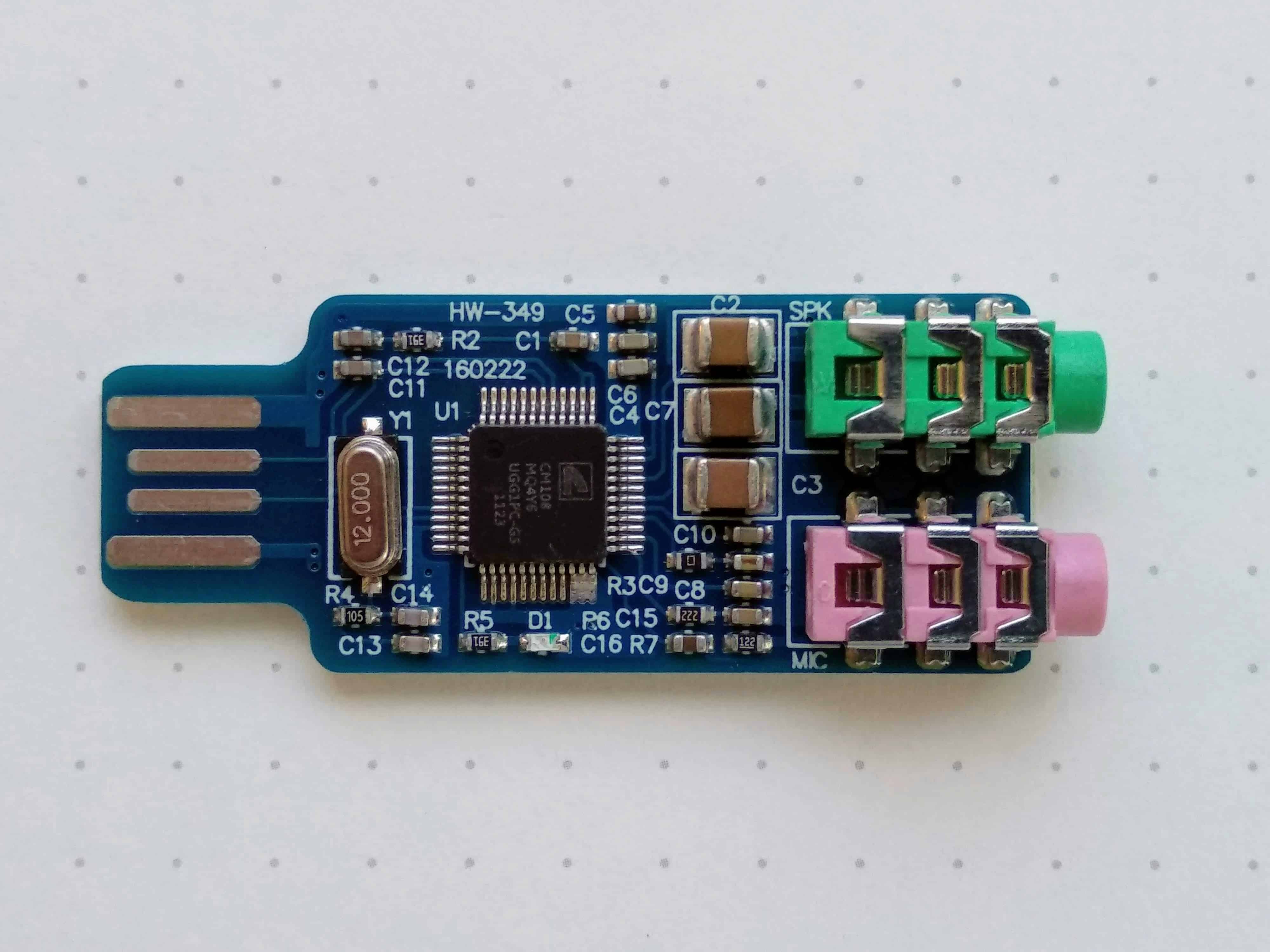
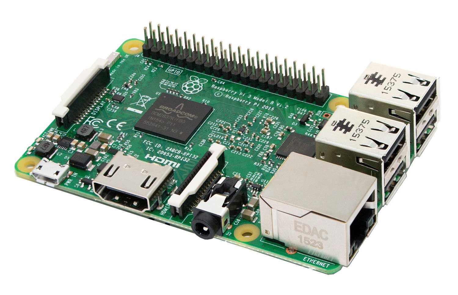 Photo 1. Above are the three main Ingredients to make this Allstar
project.
Photo 1. Above are the three main Ingredients to make this Allstar
project.
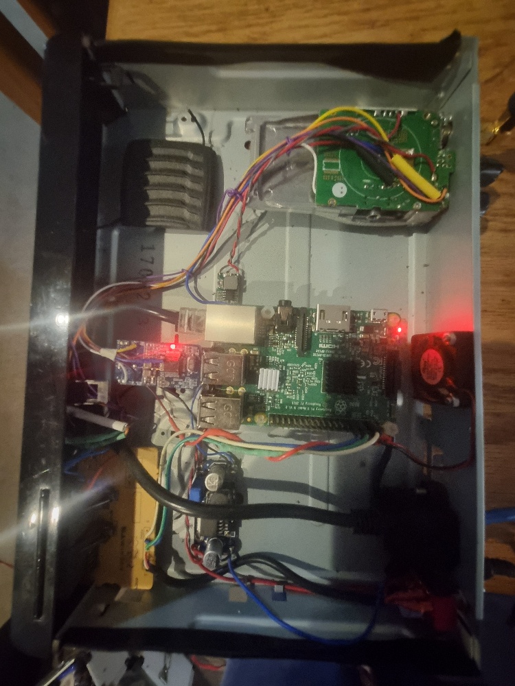 Photo 2. Top View of node
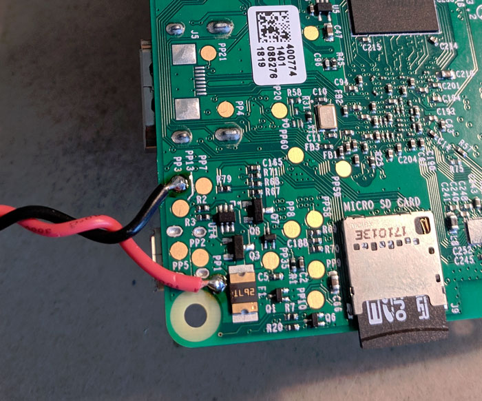 Photo 3. Power Connection on Raspberry Pi
Back to Top
Photo 3. Power Connection on Raspberry Pi
Back to Top