for further tips to help with construction
of this project.
Assembly.
Start with the resistors, install R1, (4K7) Next R2 And R3.
Next install the FET transistors Q1 and Q2. If you plan to fit any
heatsinks to these FET's then you will need to source these first as
they do not come with the kit and it is best to leave them out for now
until you get the heatsinks, then put each FET onto the heatsink first,
and then install them onto the PCB.
The reason doing it this way is to make sure the height of the FET's
legs are correct when fitted. When using a heat sink, you will also need
to make sure that the heatsink does not short out on any components
installed.
Optional extra. If you want to add a switch SW1. I fitted a switch
on my kit and soldered header pins on the switch, before soldering to
the board. (The switch SW1 and header pins are Not Supplied with the
kit.)
If you do not wish to add a switch, then you will need to fit a shorting
link or jumper in place of the switch.
Fuses
The blade fuses are also not included with the kit. You can go to most
dollar outlet shops and buy them. Our local dollar shops in town have
them for around $2.50
I used a 30A in F5 as I used J5 powerpole for the 12v power in. If
running HF rigs I fitted a 25A and 15A on VHF radios. This of course
needs to be rated on the current drawn from your radio so your fuse may
be higher or lower.
Photo 1.
Shows the blank PCB board before assembly. If you do not want to fit
LED's then skip the LED modification
Circuit Diagram
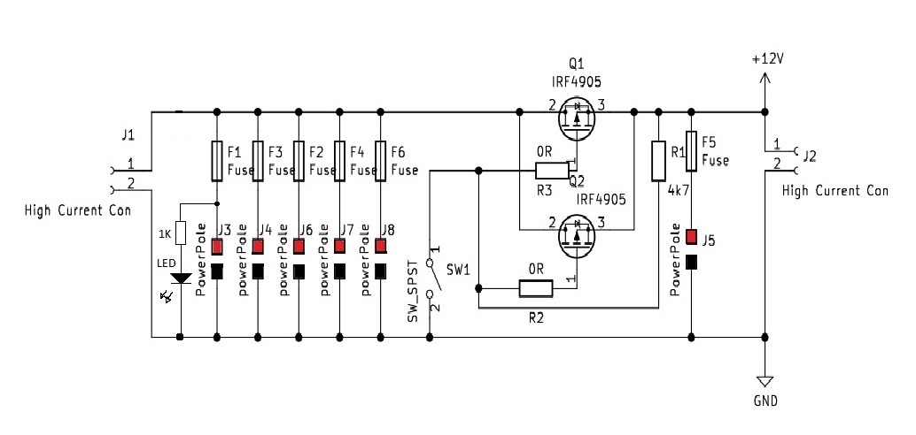
Photo 2. Shows the circuit diagram.
LED Modification.
In the circuit diagram you will notice a 1k resistor and LED at the
junction of J3 and F1. If you decide you want to fit these LED's then
you will need to modify the PCB board as shown in photo 3.
On the PCB board in photo 3, highlighted in red, you will see 3
chevrons, drill the center chevron as shown. Use a 1mm drill and once
drilled you will now need to remove a small part of the green paint
just around the hole you just drilled to allow solder to flow once you
fit the resistor.
I have shown this as a silver colour, inside the red rings that you
need to remove. Try not to scratch too much paint away and try to keep
it around the hole only, so once soldered it looks nice and neat.
The circuit diagram is showing only one LED. You need to add one LED for
each of the power poles.
I added the green LED's to show that the circuit is working, if the LED
is on. If one of the LED's goes out then the green LED that is not lit
will mean the fuse is blown. You could do the opposite and fit maybe a
red LED across the fuse which would only then light up if the fuse blows.
(This is not shown)
Photo 6. shows how each LED is fitted. the anode of the LED is joined to
the 1K resistor and fits through each hole drilled. The cathode's leg
gets bent as shown in photo 6, so the bent leg joins onto the next LED
and so on. When you get to the last LED, the connection to earth can be
seen in the middle of photo 7. I also added heatshrink over each of the
1K resistors.
The stand alone LED's and 1K resistor for F5 is
mounted differently to the rest of the LED's. Make sure you get it
around the right way. Mount the cathode leg of the LED straight down to
earth so it is inline with the other LED's and fit the 1K resistor to
anode, and the other side to the junction of F5, R1 and pin3 of Q1 and
Q2.
Anderson 25A Power Pole.
When you go to assemble these, you will need a suitable wire to solder
to the pin and to the PCB. I used the inner conductor from some RG8 coax
cable as this was a perfect size to use. Slot together the red and
black plastic power pole connectors. Next solder the wire to the pin and
fit each pin into the plastic housing. I used two lenghts of the inner
conductor, one for the red and other for black. Do one pair at a time
starting at one end and work your way over, making sure these are flat
on the board.
Reference numbers are J5, J8, J7, J6, J4, and J3.
Trim the wire, and repeat the same process for all the power poles.
Make sure you get the red and black connectors the right way round. See
photo 5, for a close up view.
Spade Terminals.
With the spade terminals we will use these as the fuse holders.
Using a pair of pliers squeeze and crimp the tip of the cable side end
so that it fits into the PCB. Also do these in pairs, and to keep these
straight, using a blade fuse while you solder them in place.
Push and fit the spade terminal onto the fuse and insert it in to F1
and solder each spade terminal onto the board. Remove the fuse and do
the same again for the rest F3, F2, F4, F6 and F5. You should now end up
with it looking like the finished unit in photo 4.
End View of Board.
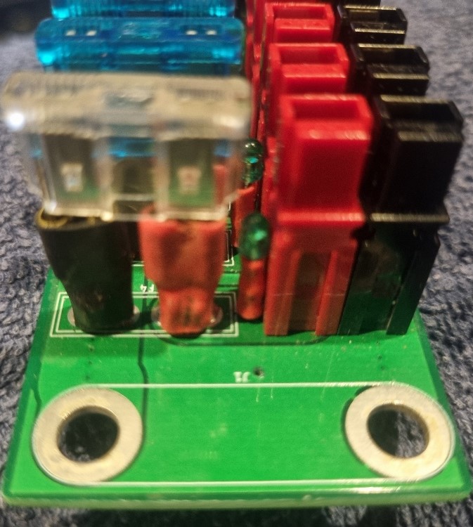
In photo 5 you can see a close up end view showing the spade terminals
and blade fuse inserted. I added heat shrink over the terminals. I used
red and black heatshrink as I did not have enough red shrink for both
terminals. Being a fuse both sides of the fuse will have 12v when the
fuse is good.
Completed in Case.
Photo 7 shows the finished project in a 3D printed case. Credit goes to
Jack ZL1IJ for design and of printing these cases.
Any issues or questions or help needed, you can email myself ZL1RJS or
David ZL1DK below.
Contacts
ZL1DK
Just click on the callsign to email David
ZL1RJS
Just click on the callsign to email Rob
 Photo 1. - DC Switch Blank PCB.
 Photo 2. - The Circuit Diagram.
 Photo 3. - Blank PCB showing marking to drill.
 Photo 4. - Complete Assembly.
 Photo 5. Side View.

 Photo 7. Completed in Case.
Back to Top