DIAMOND CP 6
ANTENNA REPAIR
by Rob Stokes ZL1RJS
Diamond CP 6 Vertical Antenna
Please note, Please read my
Disclaimer
and you understand it before
continuing.
My diamond antenna must be about 10 years old now and has been
performing very well. The antenna covers the 6, 10, 15, 20, 40 and 80
meter bands. A great antenna if you are pushed for tight spaces.
Of late I was experiencing some strange behaviour from this antenna and
it seemed it was happening only when it rained. I had a high SWR, which
went up and down then came right again. This has been going on for
months and it seemed every time we had a storm it affected the
performance. We had some very high winds one night and the next morning
I went into the shack and my antenna would not load up on any of the
bands.
Upon further investigation I took out my VNA and did a sweep across the
antenna which revealed something was definitely wrong.
I tilted the antenna over and removed the whole antenna off the mast.
I suspected the first vertical trap from the base was faulty as this
being the trap that is common to all the bands, and logic to me says to
suspect this trap as it was not loading up anymore on any of the bands.
If it had been just one band or a couple of bands, then I would have
looked at another trap. A quick measurement using an ohm meter revealed
that there was an open circuit on the 1st trap. No continuity was
measured between the two ends or to the case of the trap. Continuity was
between the case and the top end of the trap indicating the break was on
the bottom end of the trap.
Diamond CP6 Antenna Instruction Sheet
I have added the instructions sheet if needed. Just click on the link
below to download a copy.
Download Diamond CP6 Instruction pdf file to PC.
Dismantle of the Antenna
If you have installed these antennas before, you will know that the
vertical section is made in 3 parts. I decided to dismantle the whole
antenna to check it all over. You could just remove the top two sections
to get to the first trap, without removing any of the trap radials.
I did not take any photos at this point but now the antenna has been
completely dismantled almost as if it was just unboxed.
I did find that some of the screws were already loose and a couple of
them were almost about to fall out where the antenna joins each section,
so when you come to reassemble check and re-tighten. Seeing this I may
put some electrical tape over the screws to prevent it happening. With
the electrical tape, I will only use the brand "Nitto" as I totally
recommend this tape. Using this electrical tape, I have found that it is
the only tape that will not undo and sticks to itself. (Good for wiring
looms in cars also with high tempertures from the sun.) As with most
other electrical brand tapes I have tried, they are not as good and will
undo and eventually the tape will come un-done over a very short time.
I did actually end up using cable-ties, fitted over the screw heads and
not electrical tape. I will see over time if it has worked. The cable
ties will go brittle over time and may break off, but as this is not
taking any stress, they should not break and be good to stop the screw
head from coming out.
1st Vertical Trap
Upon inspection, all three of these traps have been center punched 16
times for each of the traps. You have no way of opening these traps up
unless you drill each of these punched dots. I first used a 2.5mm drill
as I tried not to create a burr once you drilled a hole as I was a bit
worried by drilling the hole would create a burr on the inside and stop
the casing from coming off. I then used a 3mm drill and drilled through
each of the 2.5mm holes. This worked out very well. I was also worried
by drilling too big a hole of the 16 punched dots, I would not get a
screw to fit. This of course now made the outer casing almost easy to
come off but with a bit of very careful persuasion it came off.
Inspection
It revealed the 1st trap was definitely broken at the bottom end of the
trap. I did some homework online to see if other Hams have had the same
problem or similar and to see how they fixed the problem.
Diamond did not think it through when they designed this antenna and the
quality control was certainly lacking, in fact, I would say a very poor
design. I watched a video on YouTube and thanks to Stan PA8C, for a good
video. It was all recorded in a Dutch language, but I got the idea on
what he had done. After the repair of the coil, I also made improvements
on the mechanical construction and modified the trap by adding 2 more
rivets on each end of the trap to make it stronger.
It appears that by only having one rivet on each side has caused the
issue that once the wind blows it was rocking back and forth until
finally, it snapped the connection. I will show the extra rivets in the
photos on what I did. (See Photo 8) After reinforcing was done by adding
these extra rivets, it has indeed made it very strong and shows no
movement. I also reinforced by soldering up each side of the screw that
connects to the center of the coils, which acts as a capacitor. I saw
that in the video that his had broken off completely and although mine
had not broken yet, I soldered up on each side to reinforce it and to be
safe.
I drilled out the broken lug and added and pop riveted in a new terminal
lug and used a 4mm drill to add the lug. I then soldered the connection
terminal and it is now better than before.
Reassembly of the Trap
As I have now drilled out those pressed center punched dimples to gain
access to the trap to repair, I found some self-tapping screws just the
right size making sure not to go all the way through and short out the
trap.
The outer casing of the trap can only go on one way as the outer middle
screw on the trap makes sure it aligns up exactly the same. Once I
fitted the case back over the trap, I fitted the screw back into the
trap and then used a 2.5mm drill just to pre drill the plastic former on
each hole to allow for the new 16 self-tapping screws to fit.
I would recommend that you use stainless steel screws as not to rust.
Coax Connection
Photo 12. Shows the PCB at the coax connector it has a little PCB board.
On one side, it has one 240pf capacitor and a coil with 5 turns.
Photo 13. shows the other side which has two wound coils round a ferrite
core. The coils have 16 turns and 21 turns. It has a large capacitor of
60pf and a smaller capacitor of 33pf.
Photo 14 Shows a side on view and Photo 15. Shows it has a slot in the
pin.
Conclusion
As the first vertical trap was found to be the problem, I did not open
the other traps but measured for continuity on all the traps. It is easy
to lower or tilt over my antenna to service, if necessary, but all the
rest of the traps will be built in the same way so if you want to
reinforce the rest, then make sure you have enough screws.
My motto is" If it ain't broke, then Don't fix it."
I added the coax connector information at the bottom as I saw this online
and did not know it had this inside. Again, I did not open that, but to
show you it exists.
I hope you enjoyed the read and that it helps you to repair your
antenna.
73 de Rob
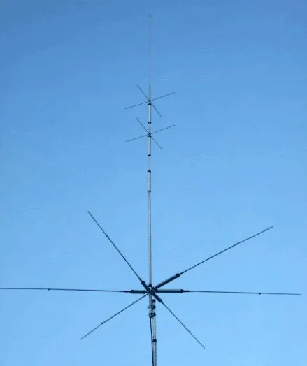 Photo 1. Diamond CP6S Vertical Antenna
 Photo 2. 1st vertical Trap (Lower Trap of 3 verticals)
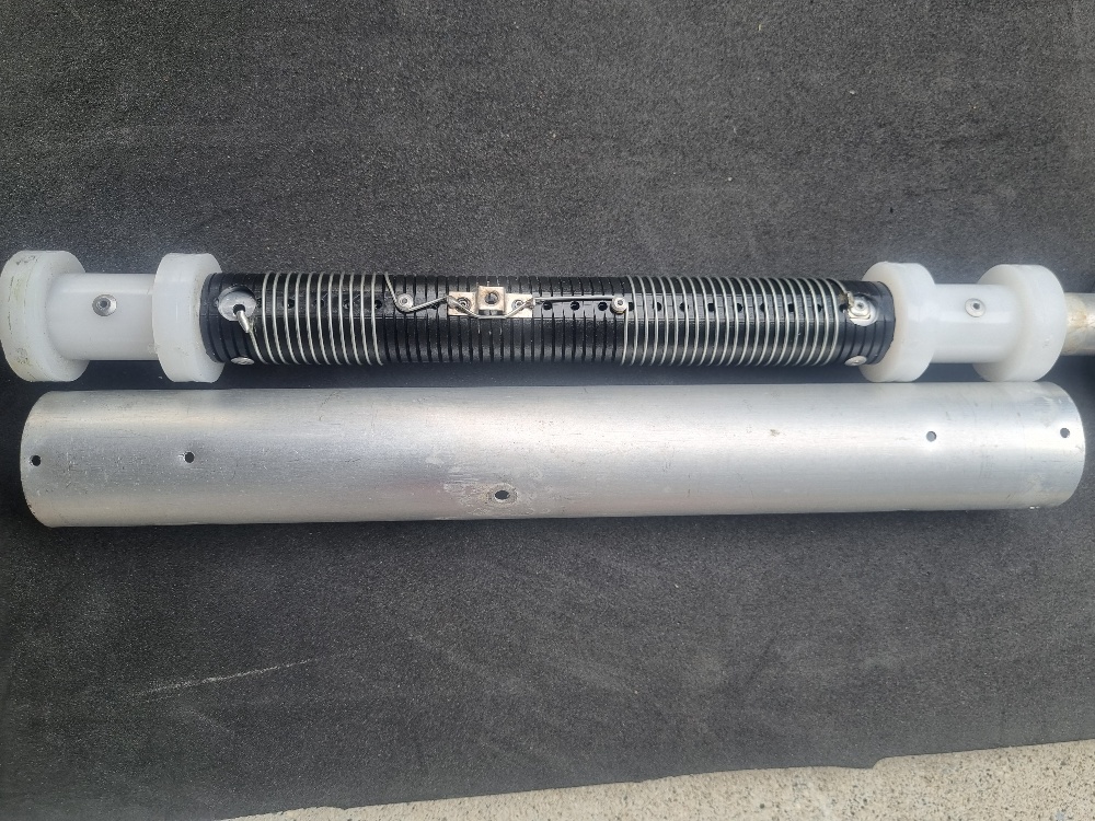 Photo 3. Trap Opened.
 Photo 4. Close-up of broken trap
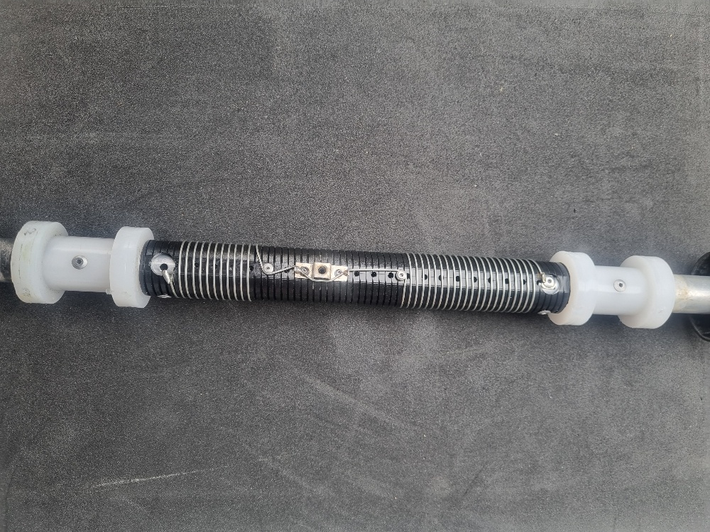 Photo 5. Trap with rivet drilled out.
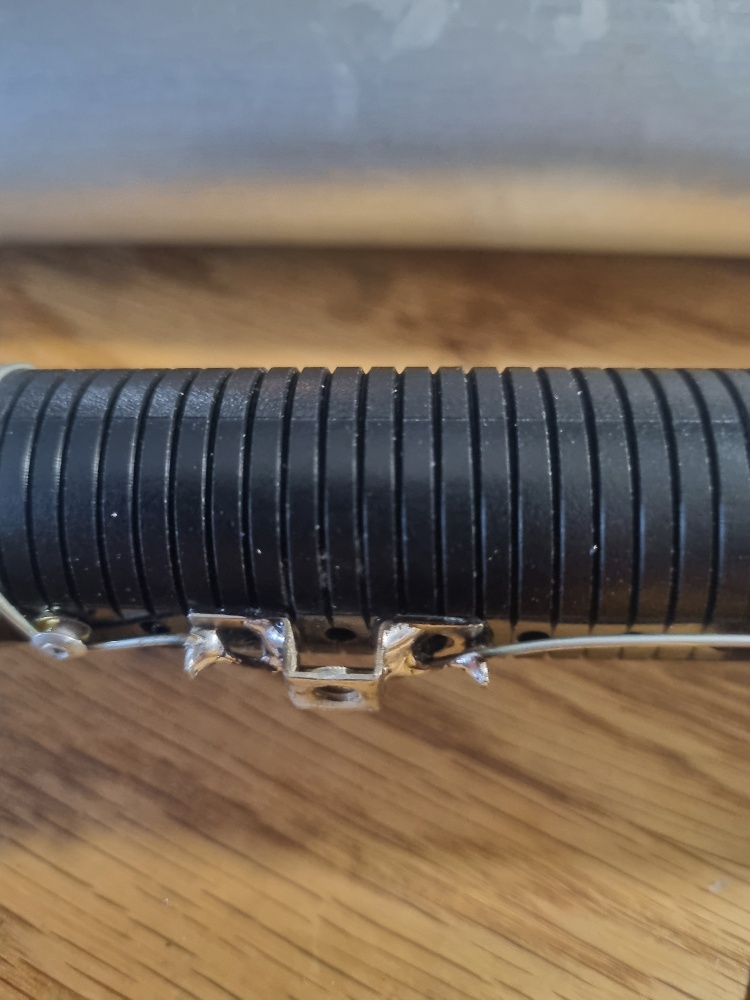 Photo 6. Capacitance nut, side view (Soldered)
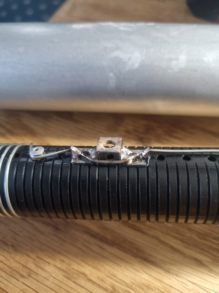 Photo 7. Capacitance nut, other angle
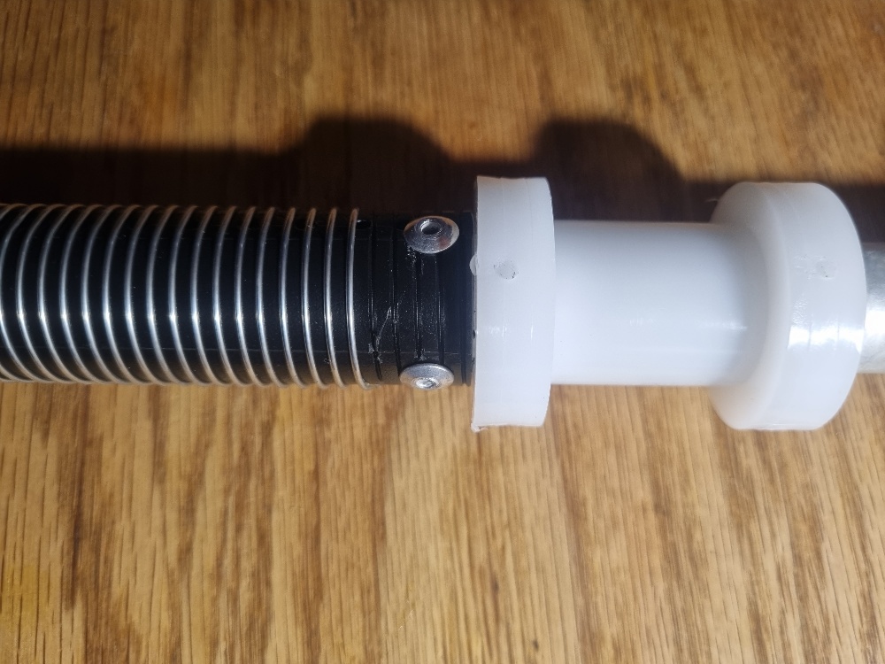 Photo 8. Extra rivets added.
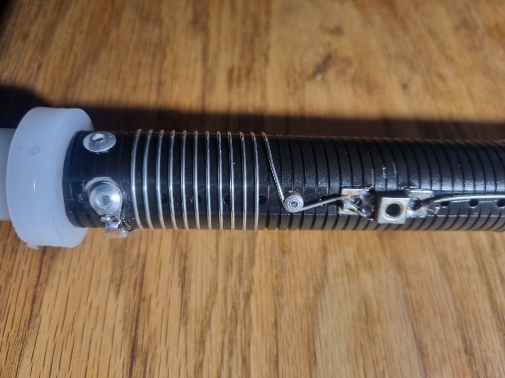 Photo 9. Trap repaired with riveted lug.
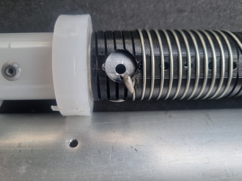 Photo 10. Close-up of drilled out rivet.
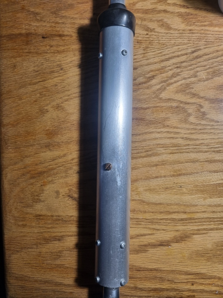 Photo 11. Finished Trap all re-assembled.
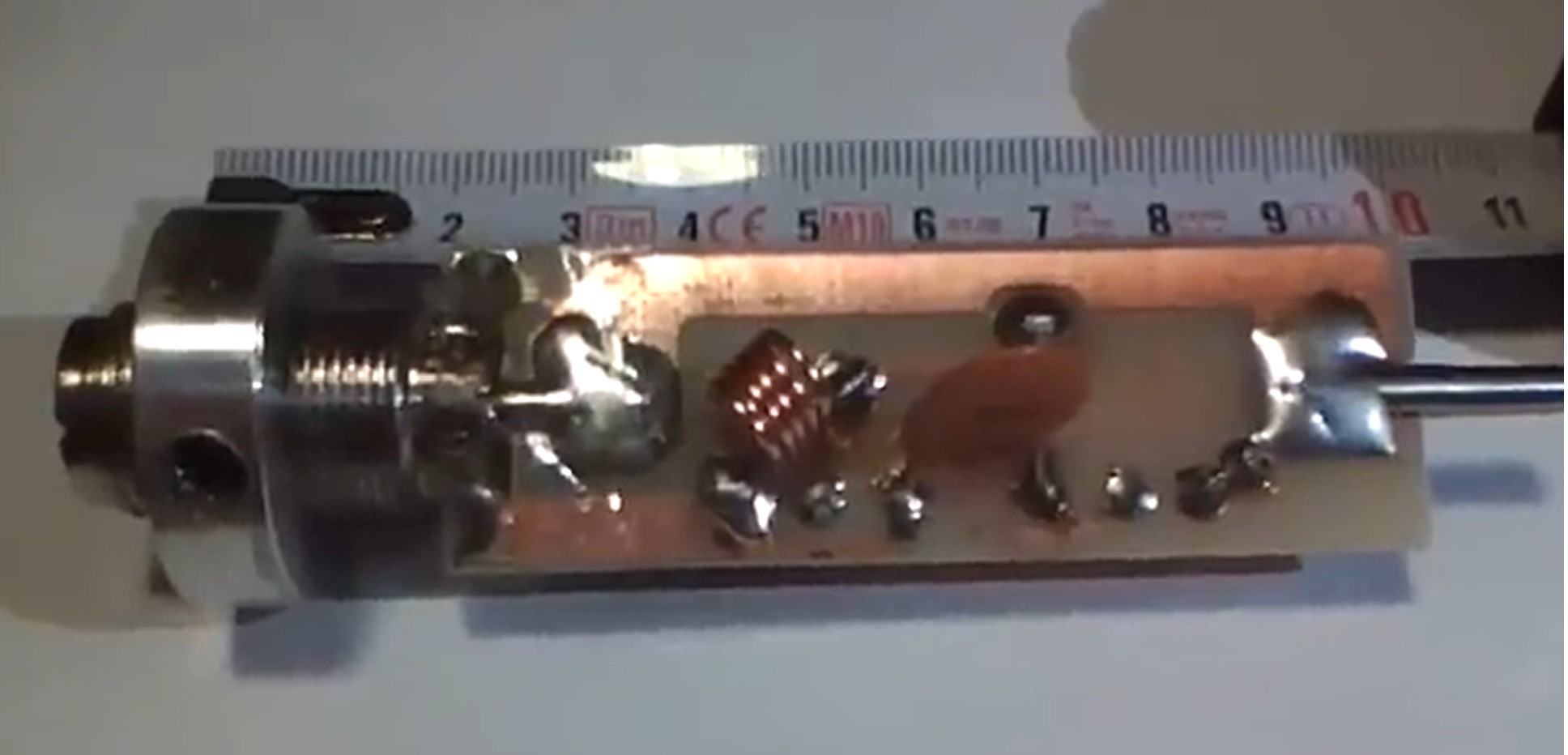 Photo 12.Showing the coax connection circuit board.
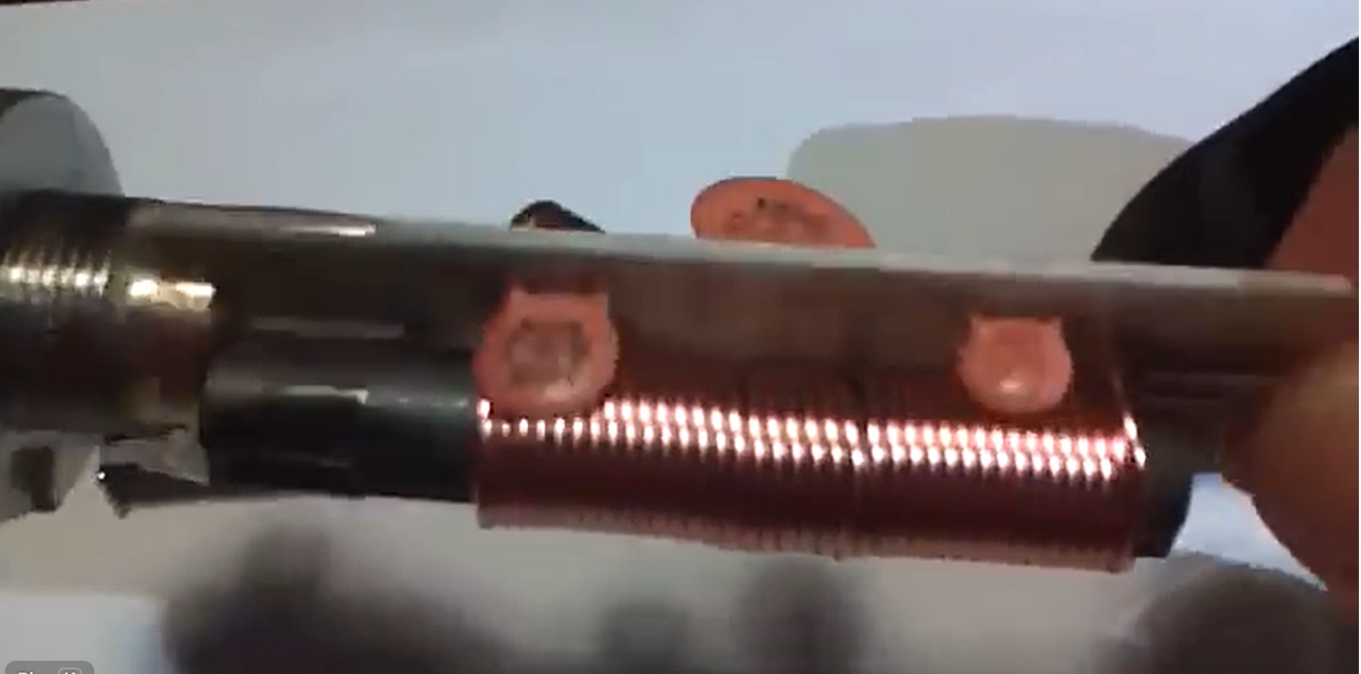 Photo 13.other side showing ferrite rod coil.
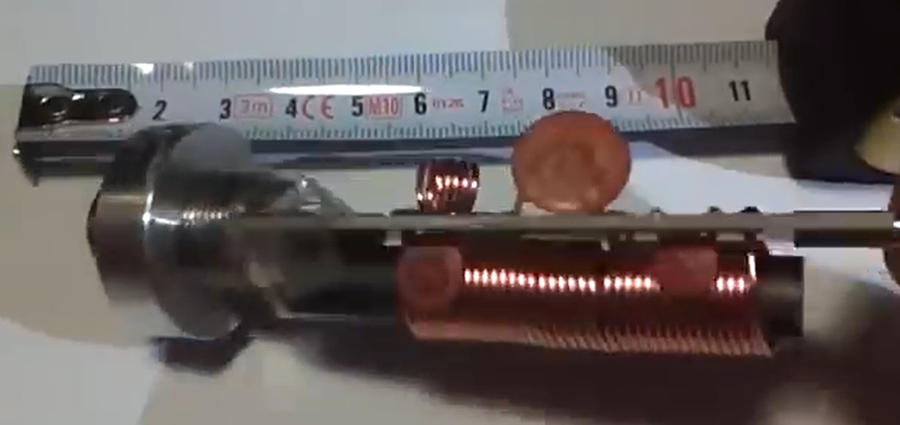 Photo 14.Side view of connection board.
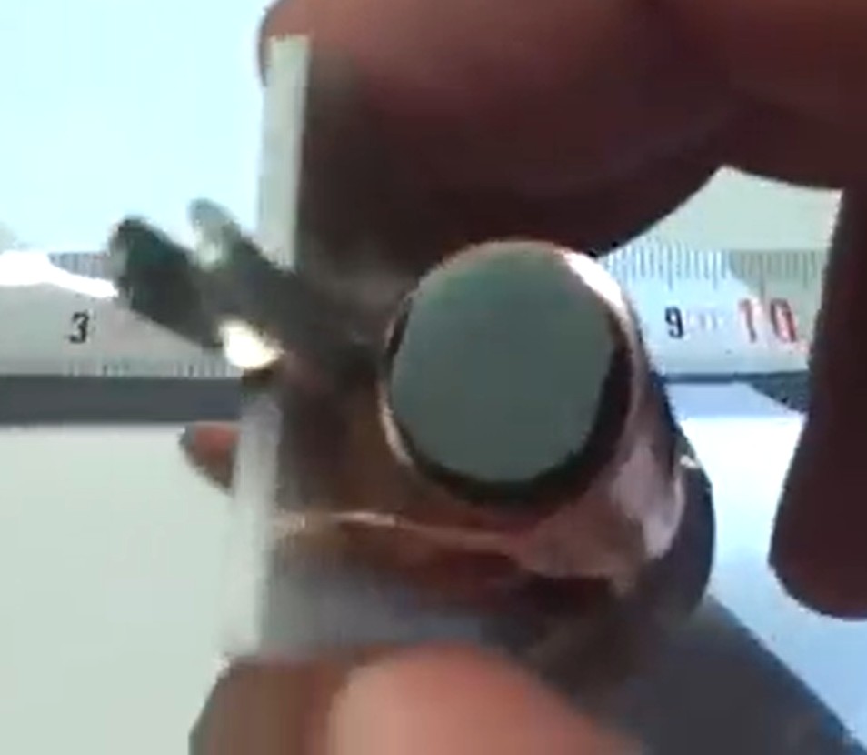 Photo 15.Showing the slot on the pin end.