
The Dipole Antenna
The Dipole Antenna by Steve Yates - AA5TB
The dipole antenna is very well known among the amateur community so this may be old hat to many. I am providing this page because the dipole antenna is often overlooked nowadays as an effective means to getting on the air. Many hams these days believe it is necessary to purchase an expensive commercial antenna or have a large antenna at great heights in order to be successful at HF/VHF communications. On the other hand, when other simple antennas are constructed many of the designs chosen require an extensive ground system to be effective.The loss due to an inadequate return (ground) system can be substantial. For an inexpensive, low-profile, high-performance antenna the dipole antenna simply can't be beat. The dipole described on this page will not give you all band performance but I believe it is better to have a very good signal on one band rather than a poor one on all bands.
The word dipole has several different meanings depending on the audience and context in which it is used. In this text it will be assumed that a dipole is an antenna that is a resonant 1/2 wave in length. The word "dipole" being derived from the word "di", meaning double and the word "polo", meaning electric (or magnetic) pivot. Therefore, a dipole has 2 electric poles (at the ends) of opposite polarity at any given instance. A dipole can be fed with RF energy anywhere along its length although center feed is the most common followed by end feed.
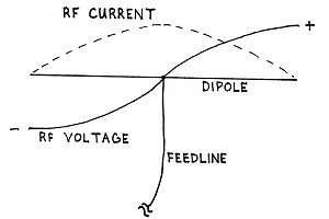
Photo 1.
Dipoles are very easy to construct and they are guaranteed to work, even if they must be installed at low heights. They are independent of ground by nature and therefore require NO ground to properly function as an antenna. If fed in the center, no matching network is usually needed since the impedance is very close to that of standard 50-ohm coaxial cable although the impedance does very slightly with the height above the ground.
Some variants of the common dipole are the end-fed halfwave antennas such as the End-Fed Zepp (originally strung behind Zeppelin airships), and the VHF J-Pole which simply uses a transmission line transformer instead of a tuned circuit to match the coax to the high impedance at the end of a dipole.
_____________________________________________________________________________________________________________________________________________________
How to Construct a Dipole
1. First, find some wire. The gauge isn't critical although it should be strong enough to support its own weight without breaking. The thicker the wire the greater the operating bandwidth of the antenna. Also, some local codes may require a certain gauge wire for outdoor antennas. Often 12 AWG is required. If invisibility is a requirement, then use as small as you can get away with. Insulated wire will work fine and in fact I recommend it.2. Next you will need to cut the wire for the frequency at which you want to operate. The wire needs to be equivalent to a 1/2 wave in length of course and the tried-and-true formula below will get you in the ball park:
Length (feet) = 468 / Frequency (MHz) or Length (meters) = 144 / Frequency (MHz)
I usually add a enough extra length to these dimensions to account for whatever I need to wrap around the insulators. Using these dimensions the antenna will usually be close enough to the correct length to work well even without manual pruning of the antenna for lowest VSWR but sometimes other factors can influence the required length. For instance, insulated wire will cause the antenna to need to be a little shorter due to the added dielectric of the insulation. Also, proximity to the ground will create the same effect due to dielectric loading of antenna from the Earth.3. Find a small sturdy tree or pole and run the wire around it once. Pull the wire around until both ends meet and stretch them tight. While keeping the wires tight, walk up the length of the wire until you reach to tree or pole. Cut the wire on the opposite side from the open ends. You now should have two equal lengths of wire.
Photo 2.
4. Find 3 insulators. Dog bone insulators are the easiest to use but just about anything with insulating properties will work such as plexiglass rectangles with holes drilled in them, PVC pipe sections, cut-up sections of plastic clothes hangers, or whatever else you can find. Just keep in mind the insulators should support the weight of the wire, withstand ultraviolet radiation from the sun, and not absorb moisture. If you plan on using anything greater then about 100 watts of power, I would highly recommend high voltage insulators designed for the purpose at the ends of the dipole. The center insulator will only have a small voltage across it and therefore isn't nearly as critical.
5. Now strip, if needed, enough wire to wrap around each insulator and wrap several turns around back onto itself. There should be a wire attached to each end of the center insulator and one insulator to the end of each free wire.
6. This version of the dipole will be fed with coax cable. For 100 ft runs or greater choose RG-8 or similar for 14 MHz and above and RG-58 for below 14MHz. For less than 50ft, RG-58 will be adequate for 30 MHz and below. RG-8M style coax will be adequate for up to 100 ft lengths below 30MHz. Prepare the antenna end of the coax by first cutting the vinyl off of above 4 inches of the end of the coax. Next, with some needle nose pliers reach in between the braids of the outer shield and grab the center conductor and its dielectric. Do this near where the vinyl starts again. You should be able to pull the center conductor out from within the shield. This should leave you with two separate conductors.
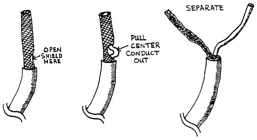
Photo 3.
7. Some sort of strain relief should be provided for the coax. My favourite method is to simply wrap the coax around the center insulator once and Ty Wrap or tape the coax back onto itself. The two stripped ends of the coax will now be hanging down. Solder one conductor to one antenna wire and the other conductor to the other wire. Be sure that the points where the antenna wire wraps around itself near the center insulator is soldered too. Since a large amount of current flows in the center of a dipole, it is very important to have low resistance and preferably soldered connections.
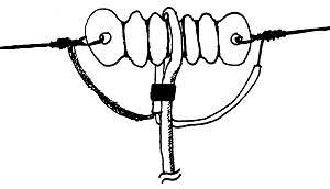
Photo 4.
8. Water proofing of the exposed coax connections must be provided. Thoroughly spraying the connections with a sealant is the easiest.
9. Since this is supposed to be a simple antenna, I didn't include a balun in this design. A balun (balanced to unbalanced transformer) is often used to choke off undesired RF currents from flowing externally on the coax cable. This can occur due to the unbalanced nature of the coax. As long as the feedline is run a right angles to the antenna wire for about 1/4 wavelength or greater and the antenna length / coax diameter ratio is large there usually isn't much of a problem. However, at the higher frequencies where the antenna is shorter this can become a problem. My favourite simple method to reduce these stray currents is to simply coil up about 8 turns of the coax into about a 6-to-8-inch diameter circle up very near the antenna. You will have to be the judge to determine if the added weight at the center of your dipole is worth the effort.
10. To support your dipole, you will need some rope to attach to the end insulators of your dipole. Wire can be used although it will capacitively couple to your antenna somewhat and may make tuning a bit of a trick. I prefer to use rope.
11. Now your antenna is ready to be strung up. It can be hung by the ends as a horizontal flattop, supported in the middle as an inverted-vee, or just about any other way you can get it up. Here are some rules of thumb to follow:
- Do NOT install your dipole ANYWHERE near power lines!
- Try to keep your dipole symmetrical. This ensures that you are feeding it in the electrical center.
- The antenna may be folded to accommodate small lots/sections, but try to keep the bends shallow and no more acute then about 90 degrees. Fold the ends before you fold the center. The larger the center area, the greater the efficiency.
- The higher the better for long distance work, especially at low frequencies.
- A low antenna can work very well on short paths on 10 MHz and below. This is called NVIS (Near Vertical Incidence Scattering) and is a popular mode with the military and government.
- The dipole can be strung vertically although this would lend itself better to end feeding. For VHF use horizonal mounting for SSB and vertical mounting for FM.
- If you can't meet all of the above criteria, just put it up the best way you can.
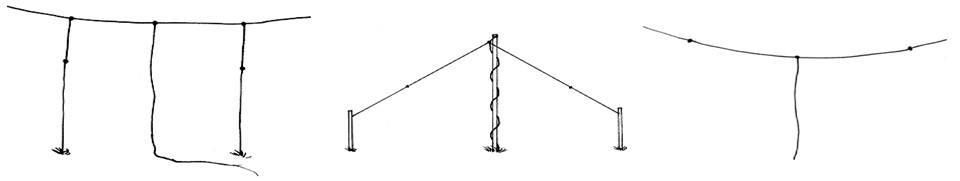
Photo 5.
12. Now that your antenna is up, it's time to check its VSWR. While transmitting at the frequency that you cut the dipole for measure the SWR. If it is less than 2:1 it will perform fine and no one will ever notice a difference if you try to improve upon it. Your radio might. Some radios will reduce their power output if the VSWR goes much above 1.5:1. With a little length adjustment this should be easy to accomplish. Measure the VSWR at the ends of your band. If the SWR is lower at the lower frequencies then it is too long. If it is lower at the higher frequencies then it is too short. Adjust the length at about an inch at a time until it is where you want it. If the antenna is too short simply attach a pig tail of wire at the end of each wire. Be sure to make the length adjustments to both wires at the same time. If for some reason the VSWR is still too high at its lowest point, try adjusting the height of the antenna. As mentioned earlier height will affect the overall impedance of the antenna.
13. Now that your antenna is all checked out be sure to solder the ends if needed so that they won't pull loose from the insulator. Now get on the air and enjoy the really inexpensive antenna that you built!
_______________________________________________________________________________________________________________________________________________________
© 2024 ~ ZL1RJS